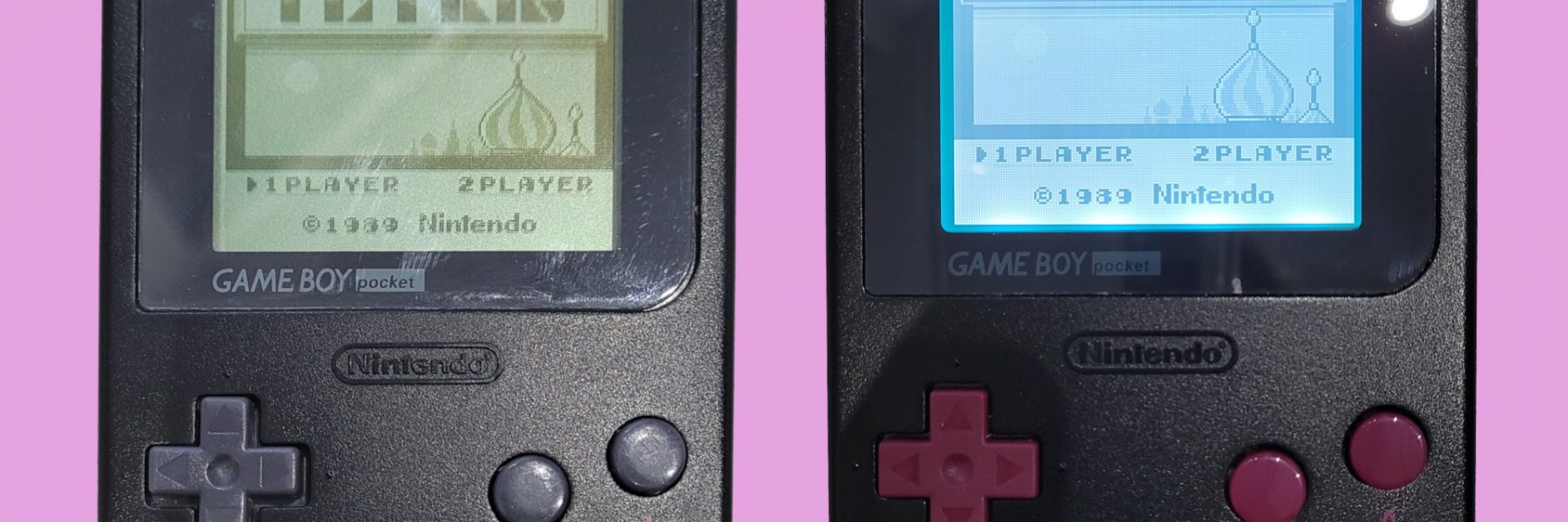
Even if you can now put an IPS screen on a Gameboy pocket, adding backlight (and bivert) is a cheaper solution and it’s still a good way to enhance the screen.
Adding backlight without bivert is quite acceptable on the Gameboy pocket, but you loose a lot of contrast. However, together with bivert mod, the screen become better than the original non-backlit screen… And this also accentuate a little bit the ghosting effect of vertical lines.
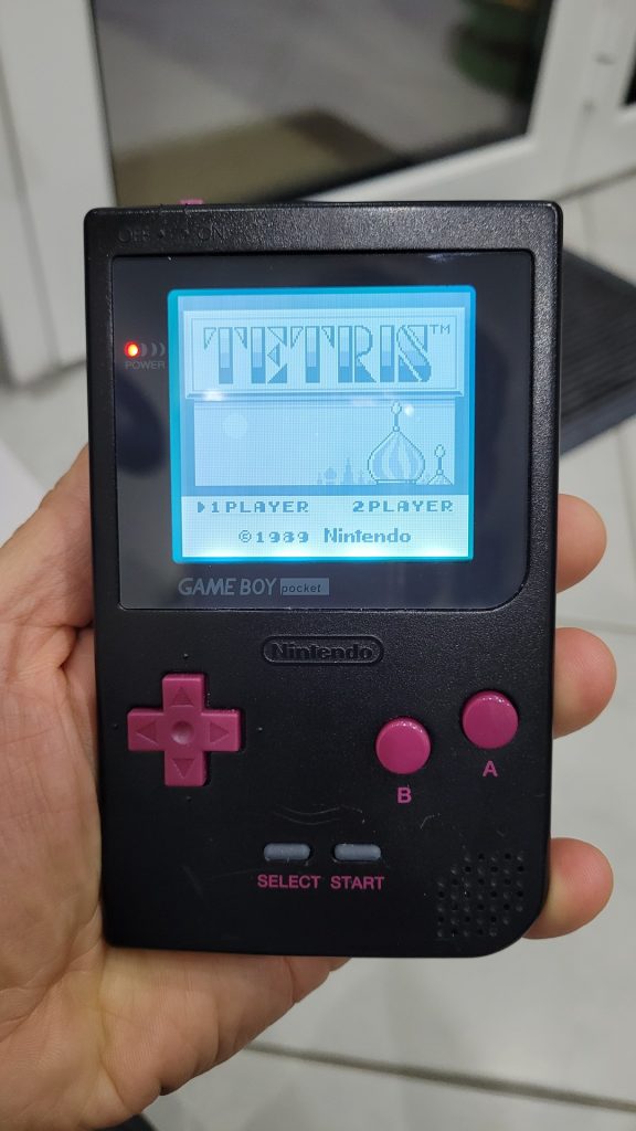
This article is the story of my pimped GameBoy pocket
Needed materials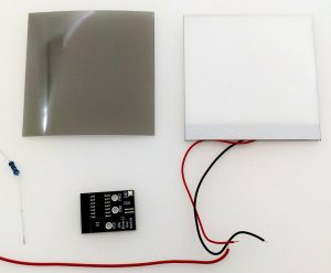
- Backlight kit for Gameboy pocket
- A “bivert” chip : I used a the model for the classic GameBoy as it’s easier to install
- Dremel to make some place for the backlight module (the whole screen become thicker)
- Ribbon cable or small wires
- 2K ohm resistor (or 2 x 1K ohm in my case)
- 470 uf capacitor (10v or 16v are fine)
- triwing screwdriver (often delivered with the kit or a custom shell)
- Some silicon oil in spray (optional)
Step 1 : bivert
It seems to be a good idea to bivert the screen before adding backlight, because it’s more intrusive. You need to manipulate the motherboard in the front and the back : adding the backlight module before may ont allow to move the motherboard easily as it is really fixed only when the shell is closed.
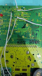
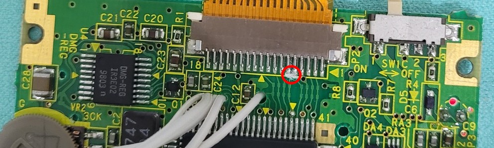
First things to do : open the GameBoy, remove the screen’s ribbon cable and add some solder to the point where the wire will be soldered (see red circle on the photo at the right)


Now, Solder the wires one by one passing them through motherboard’s holes and add a label on them or anything that could help to remember their positions.
Then solder the wires to the bivert board. The best place to fix the bivert board seems to be on top of the speaker, with some double sided adhesive. Be sure to use a 0.05mm thick or more to avoid any short circuit due to the speaker’s metallic surface.
The corresponding solder points to the bivert board are :
- P2-FR to left long pad
- P2-LDO to right long pad
- LD0 to pin 3
- LD1 to pin 1
- P2-GND to ground
- The last wire is VCC
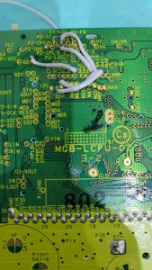
The last step is to cut to tracks that provides the original signal to the display panel, as it must now pass through the bivert chip an no more directly:
Finally, replug the screen and use a 3v power source to check if the screen still works. You can use a power adapter or a external battery holder for example. The screen should show an inverted image like this :
Step 2 : backlight
This step is not hard but required modifications need to take time as well as a great attention. They are both destructives : it will not be possible to step back except if you buy another screen and another shell.
Make some room for the backlight
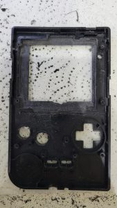
Before starting, you should remove the front protecting glass by gently pushing it from the back. You should have a brand new one in the kit, so it will be replaced at the end.
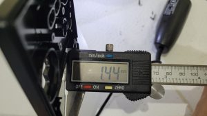
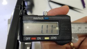
The back light panel is around 0.3 to 0.4 mm thick. Some space need to be made, else you will not be able to close correctly the case and the pressure will cause some dark spot on the screen. The orignal front face is around 1.44 mm thick around the display. It should be around 1.11 mm. You can use a dremel to carefully remove some plastic evenly around the display window.
Here are the mesure I took before and after the operation:
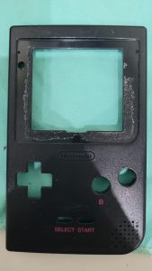
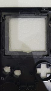
Right after the operation, the front face should look-like this (left photo). You can now clean it up and install the double sided adhesive (right photo). Then put this aside, we now need to work on the screen.
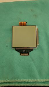
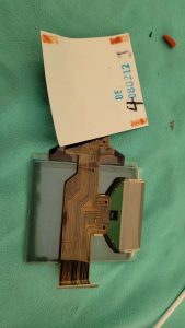
Prepare screen for back light
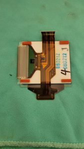
The original screen has a glued reflector on its back. It must be removed so the back light will enlight the display by the back (hmmm yes, it’s back light after all…). The easiest way is to detach a very small part of one corner with the help of a cutter or a razor blade. The objective is to be able to take the reflector between the thumb and the index. You can optionally put some silicon oil with a spray while pulling a little the reflector, this helps a lot to remove it gently.
After the operation, the screen needs to be cleaned up with either alcohol (90%, isopropyl or even some nail varnish remover). Ensure that there is no more traces, then the display can be placed on the previously prepared front panel. I used some adhesive tape to the backlight panel cannot move while I plug the ribbon cable of the display.
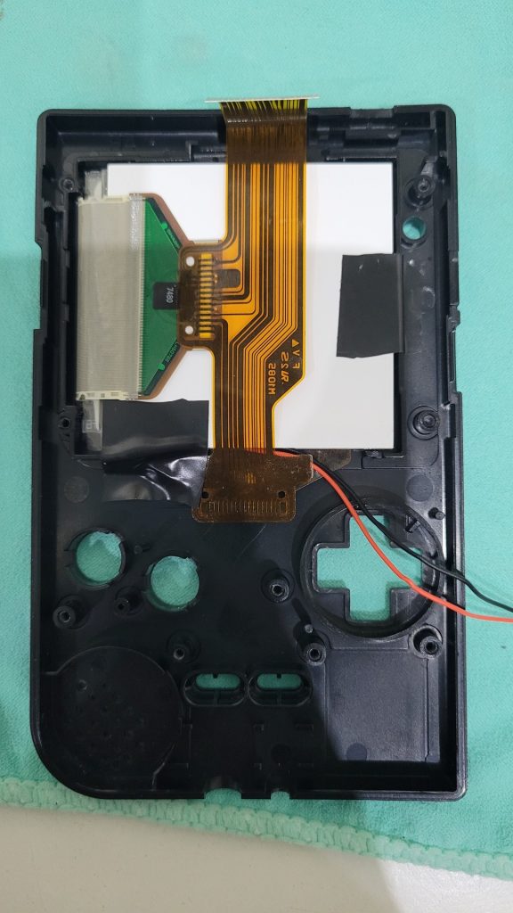
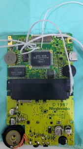
Then, arrange the wires so they can exit via the corner below the dpad. It’s now time to put the motherboard back with the bivert board.
I personnaly used the 5v pin from the internal dc regulator instead of the 3v out from the battery. It needs a greater resistor (2K ohms) than the one which comes in the kit , but the light stay bright and stable during the whole batteries life time, even with NiMH ones. The drawback is that a decoupling capacitor is required to make the system more stable with all games (but not with a flash cart). I used a 16v 470 uf beeween the positive and the negative of the 5v DC-DC regulator.
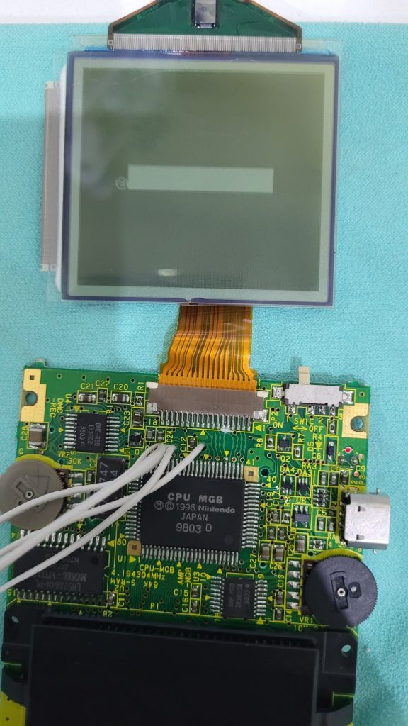
Below is how I soldered all the items. As you can see, I used two 1k resistors, because I did not have any 2k.
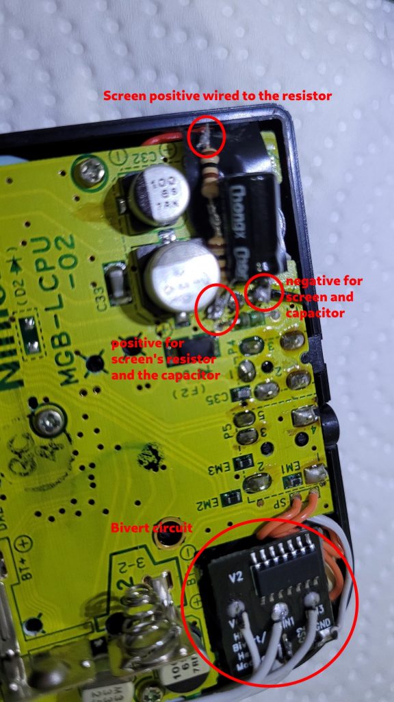
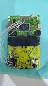
And the following show the whole motherboard before remounting the back of the shell:

Here is the final result, with new buttons !