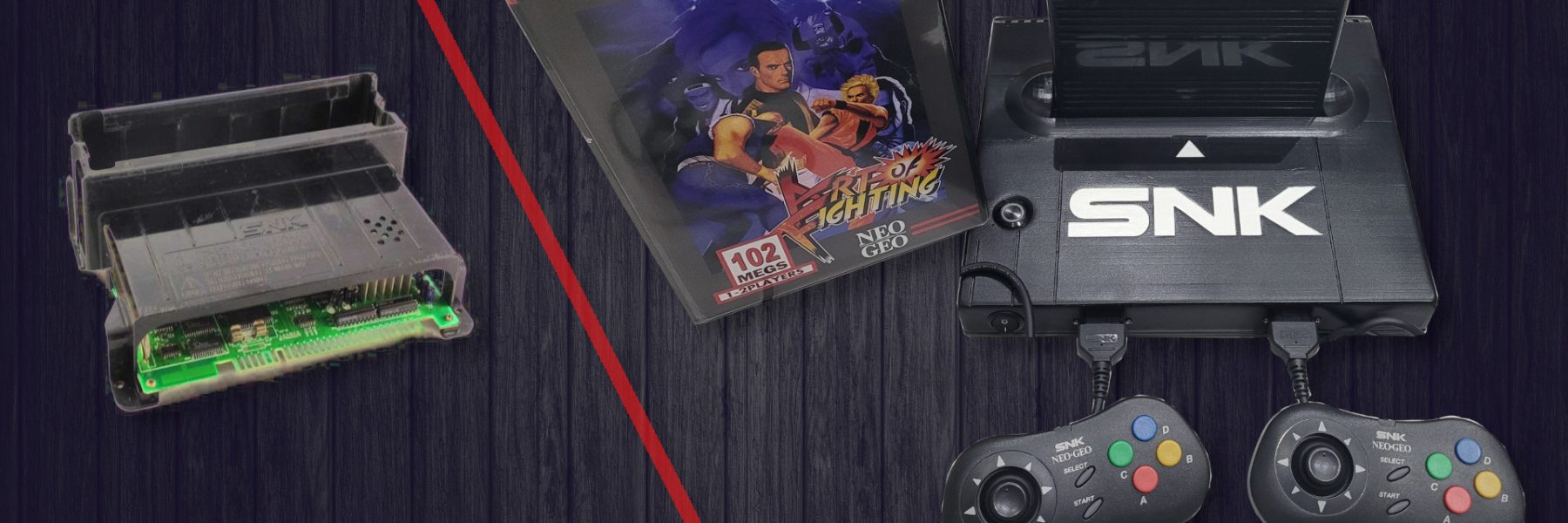
The Neo Geo is well known as the most powerfull home video game console of its time. Back in 1990, the AES system (home console) had the exact same hardware as the MVS system (arcade model). The home console was priced very high. And it’s no surprise that today with the growing interest for retrogaming, the home system as well as the games are very expensives. The MVS slots are way cheaper, but not usable as is, unless you own a jama compatible arcade cabinet. But the internet offers all needed documentations and ressources to transform a MVS slot into a Neo Geo home console.
This is the story of my home made Neo geo MVS consolization which is highly inspired by a very googd tutorial on Jamma Nation web site…
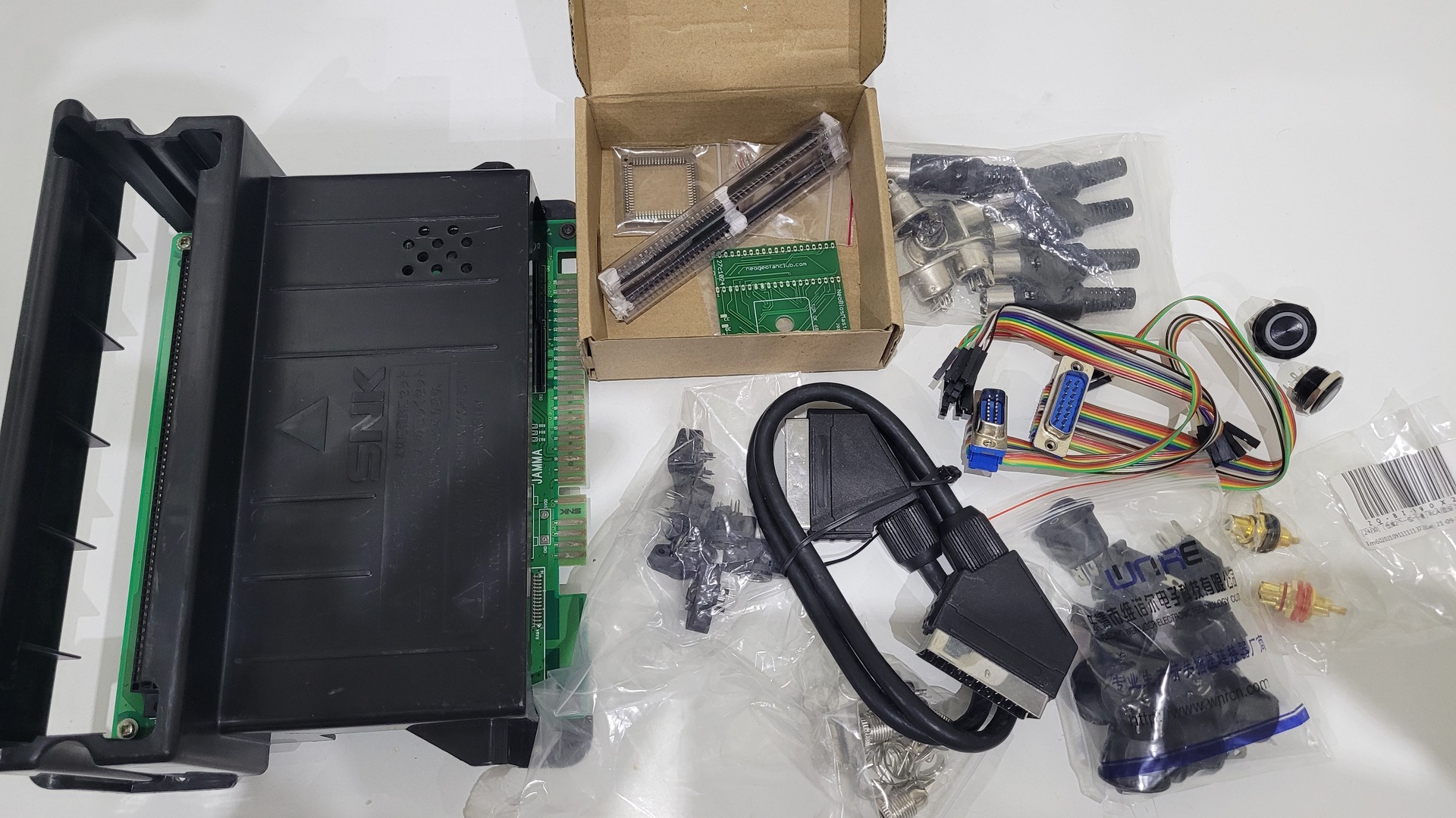
Used materials
- A MVS MC-1C, which is the only one that offers top loading for cartridges
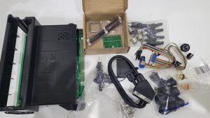
- Neobios masta for MC-1C motherboard, with battery kit and an unibios 4.0
- A 19mm round backlit momentary switch (I took mine from “jotta store” on Aliexpress)
- A 5.5×2.1 mm male power connector jack for pannel mount
- 5V 4A power supply with a 5.5×2.1 barrel connector
- A 20mm round on / off switch
- A 8 pins DIN “C” shape female connector for pannel mount
- A Megadrive 1 / Master System RGB Scart cable (“C” shape)
- 2 x DB15 connectors wired with dupond connectors

- A LIR 2032 Battery
- 2 female panel mount cinch connectors
- 2 male cinch connectors (or any cable that you could cut)
- Some colored wires / old ribbon cables
- Desoldering pump and a solering iron with fine tip
- Hot glue
- A way to 3D print a 30×30 cm chape
- 2 orignal Neo Geo controllers. I personnly chose Neo Geo CD joypads
- 2.5x20mm nuts and bolts to fix the motherboard
- Spray paint primer, mat black and transparent varnish
- 4 lugs
- Some luster terminals

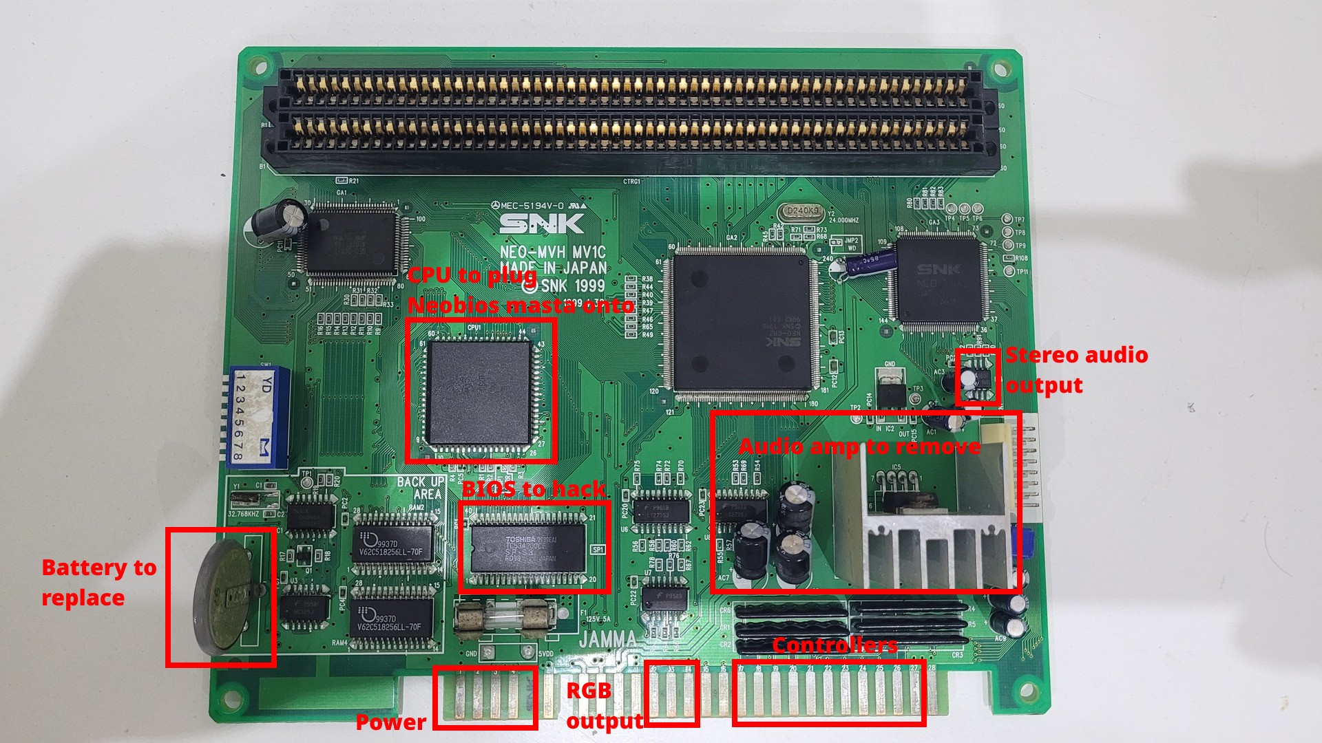
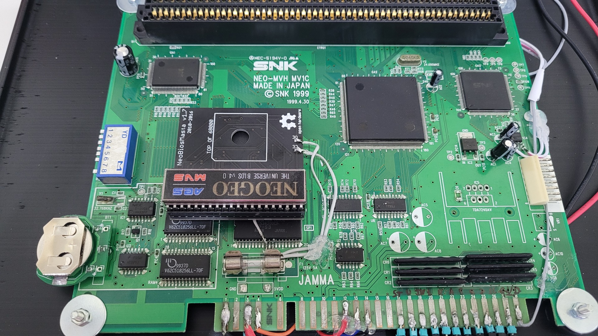
Overview of modifications
Here is an overview of where we need to do modifications on the motherboard.
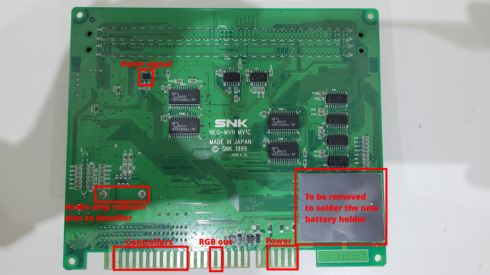
Preparing the board
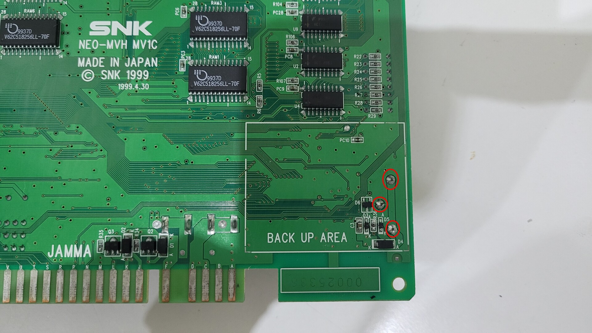
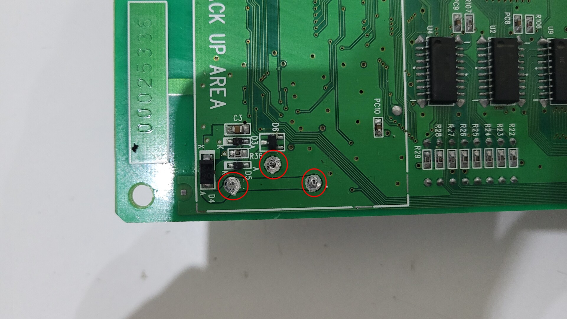
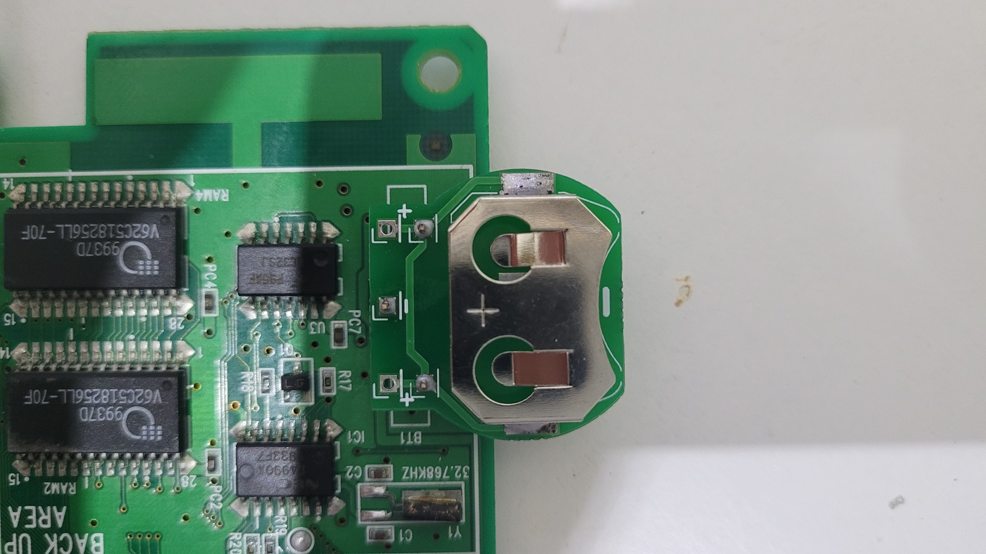
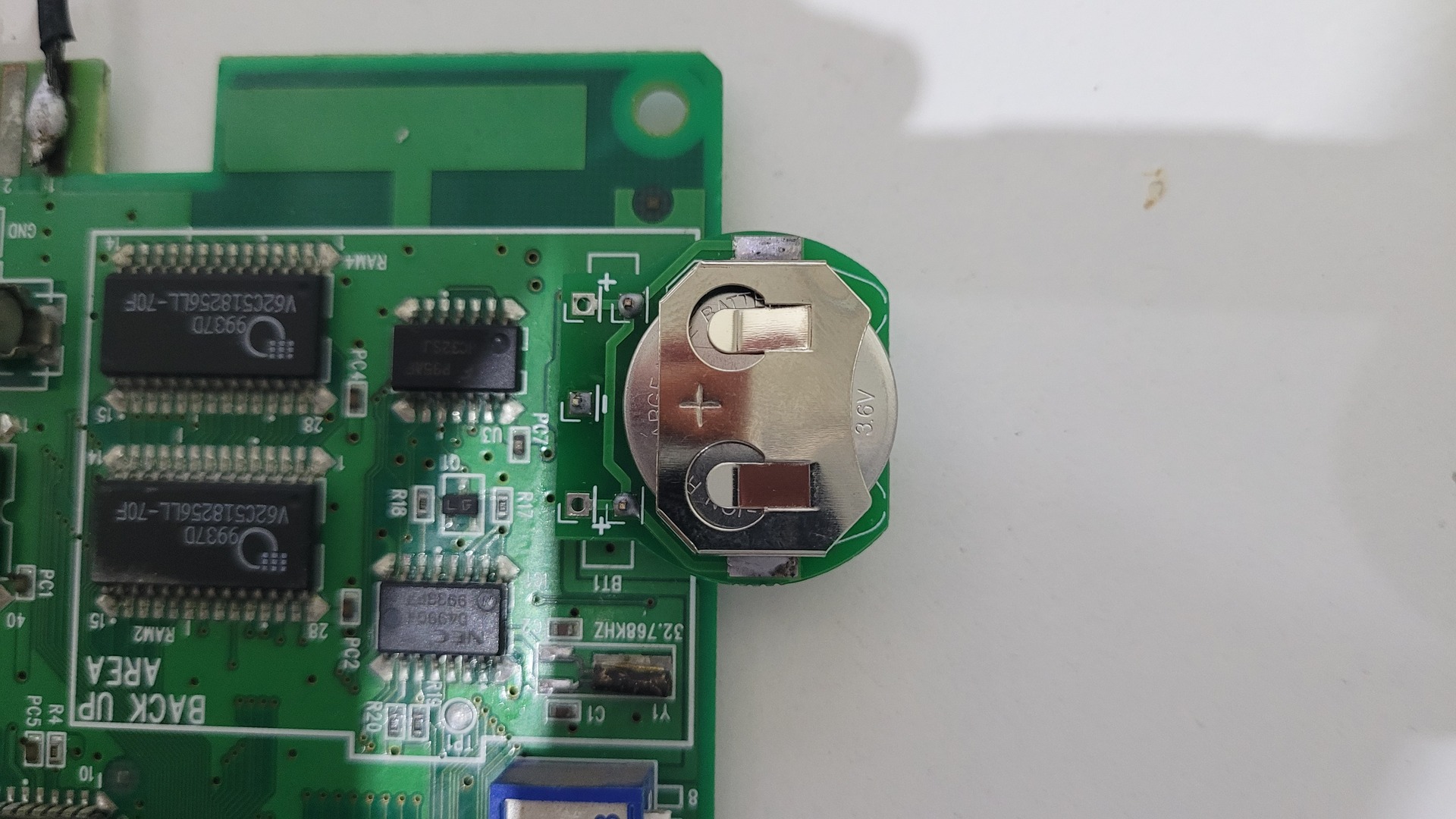
Backup battery
The idea is to replace the old battery which is solered to the motherboard, by a socket with a removable LIR battery 2032 (3.6v / 45 mAh). To do so, the gray plate on the back of the motherboard must be removed. I used a desolering pump to remove the old battery.
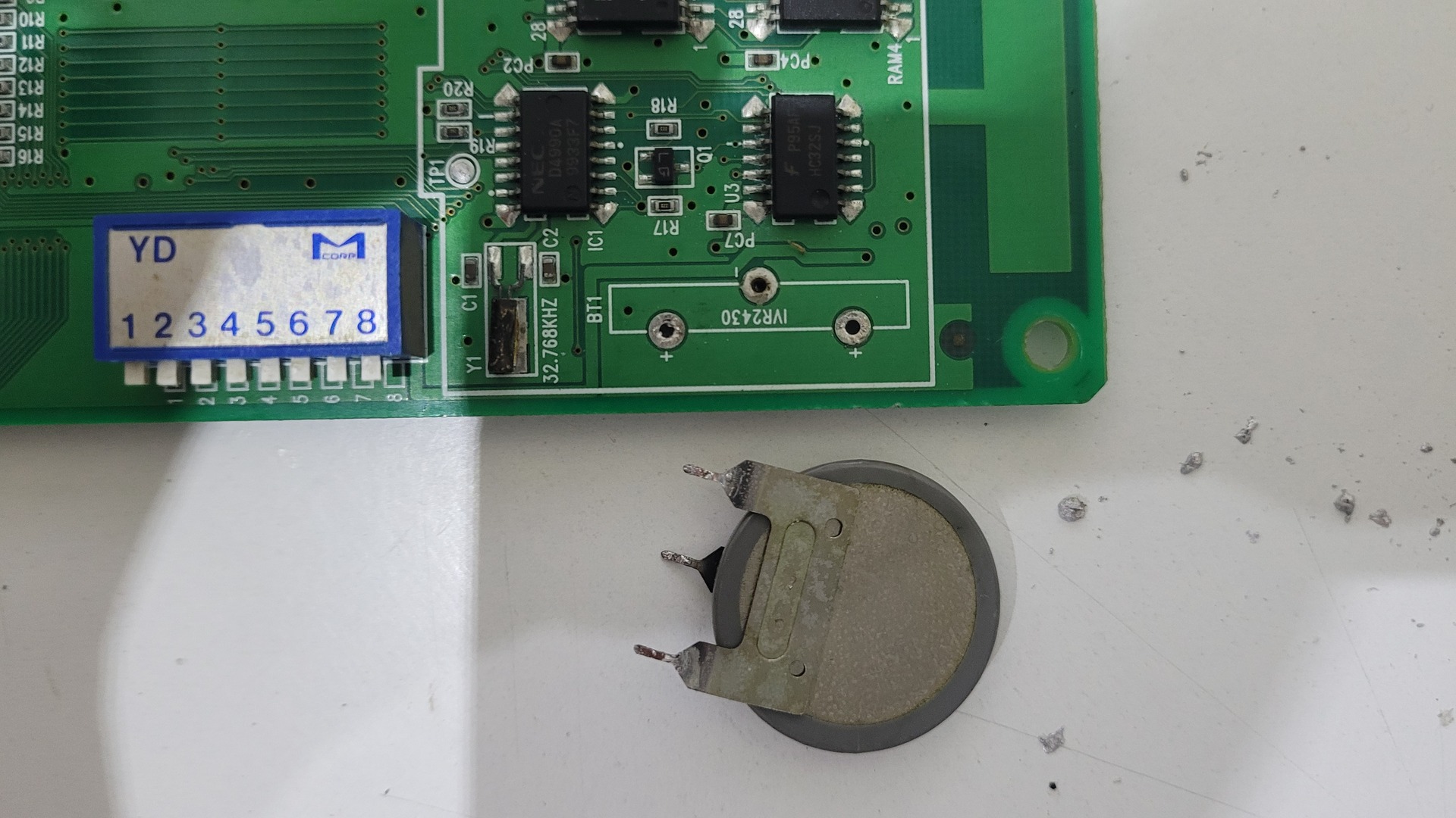
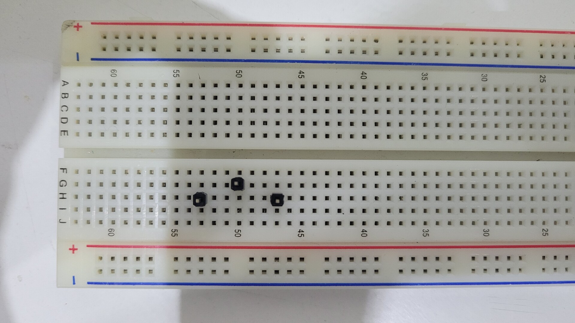
The battery kit that comes with the neobios mastas has to be assembled. A protoboard can help to solder the 3 pins
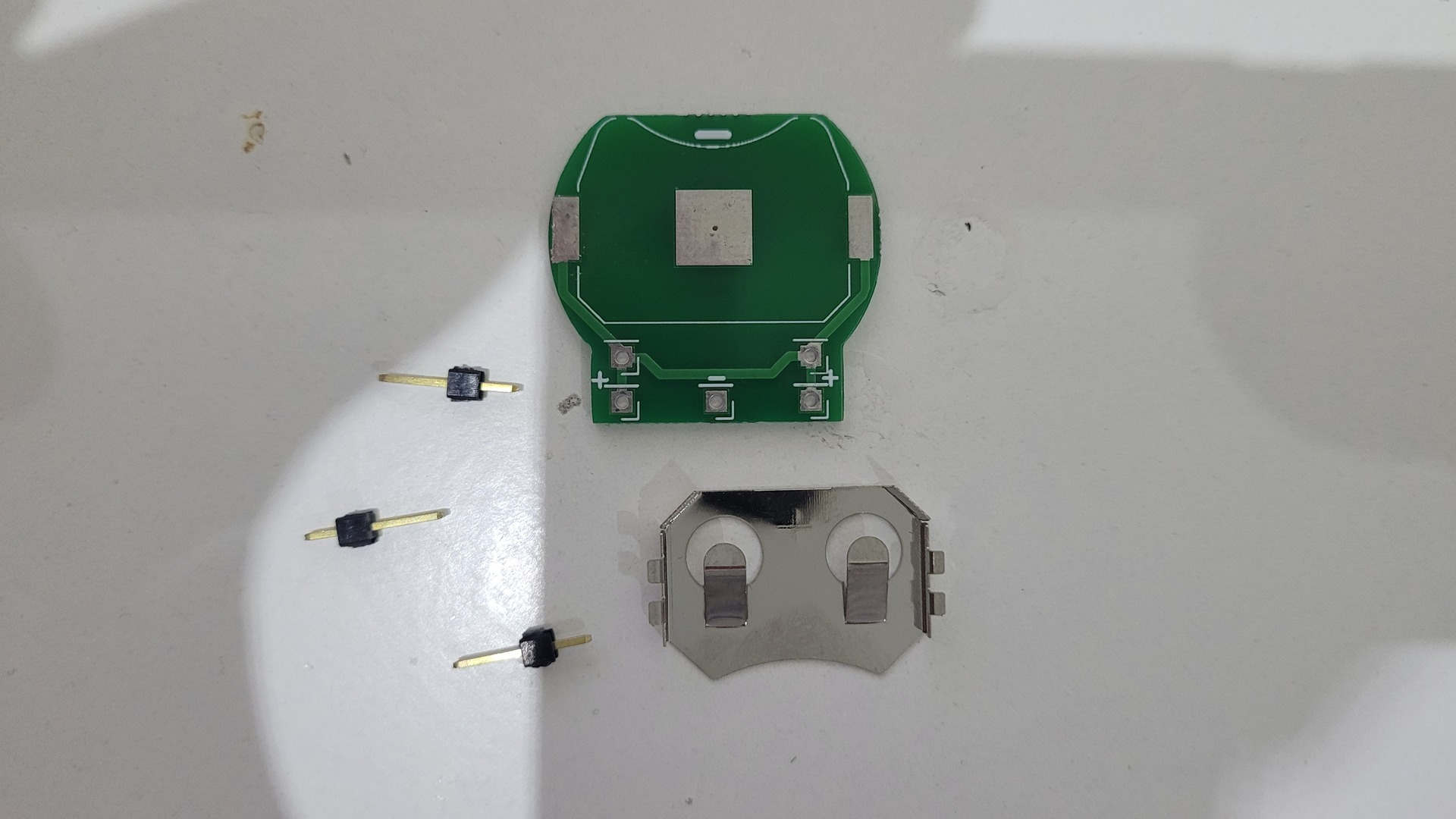
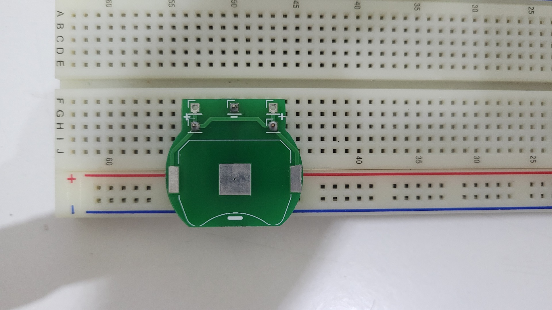
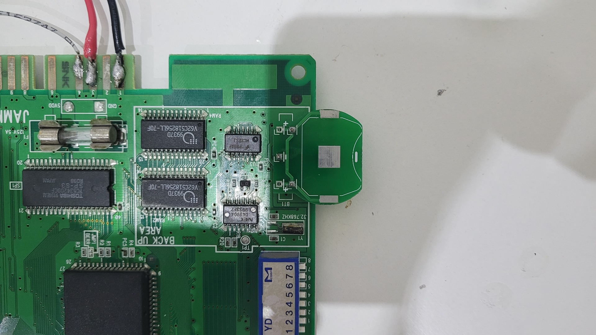
Finaly, the kit can be soldered to the motherboard with its metal shield and the battery can be put in
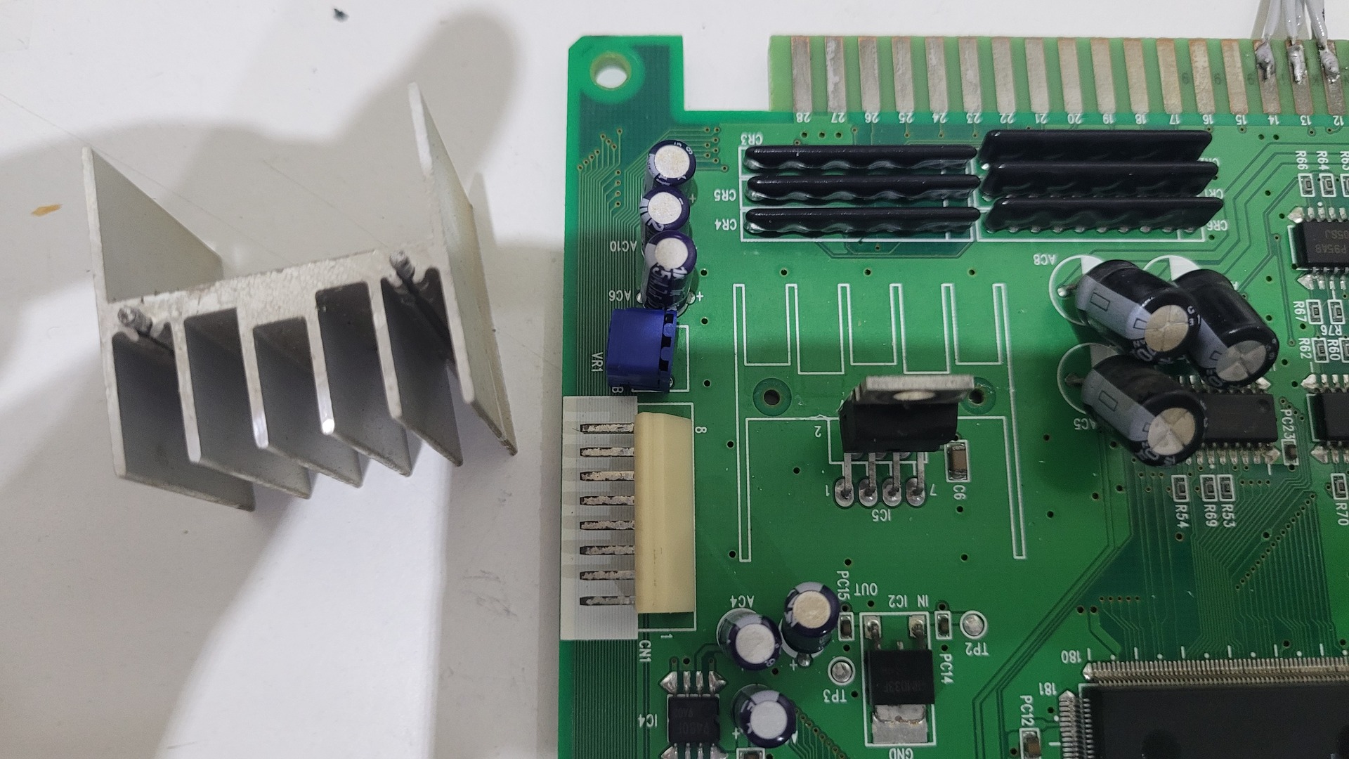
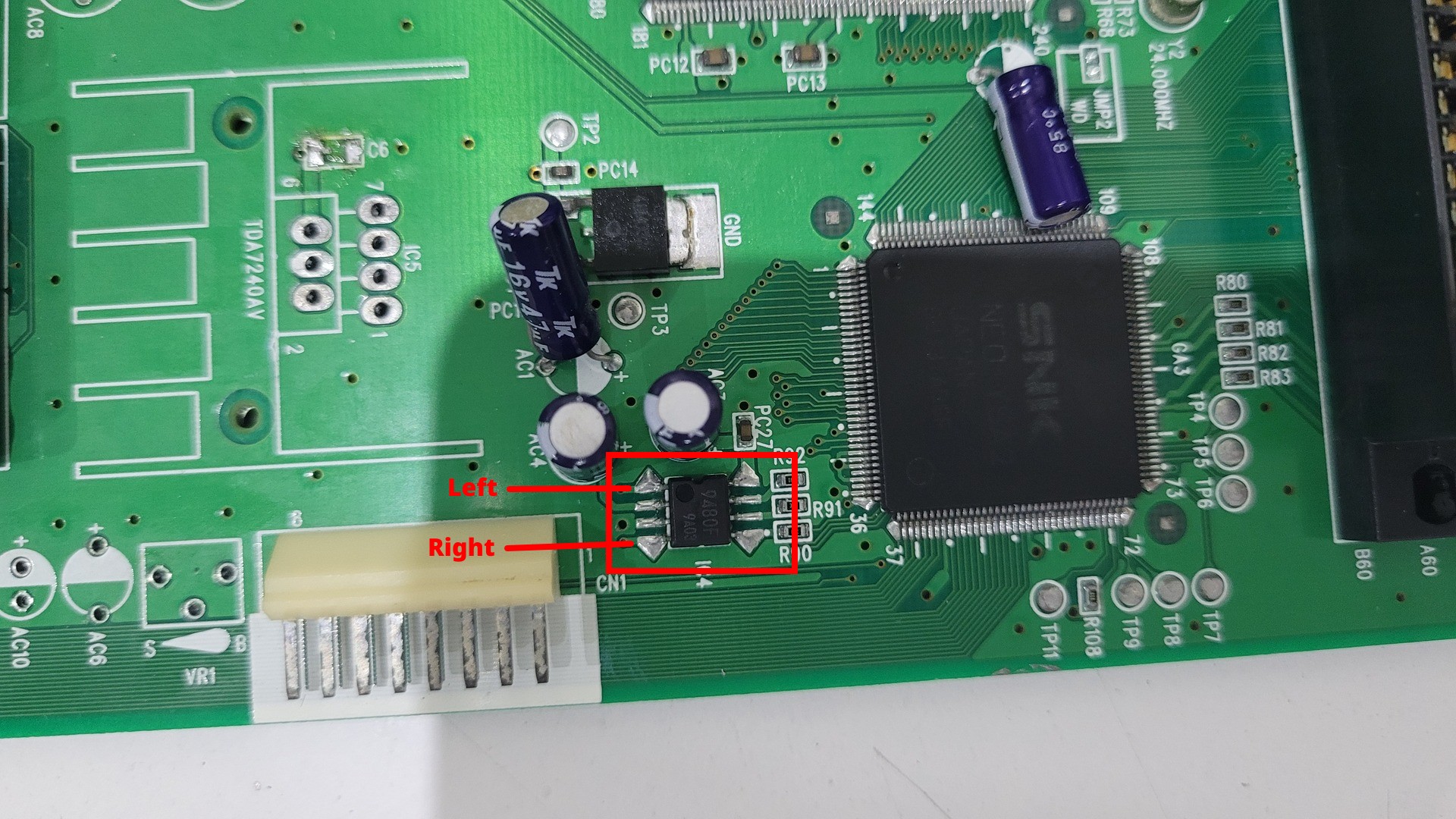
Stereo audio
The motherboard comes with an integrated audio amplifier which output a mono signal. In order to use a standard TV (LCD or CRT), we need a non amplified audio signal. Moreover, the motherboard provides a stereo audio signal which feed the amplifier. So the goal here is get the stereo signal. In addition, I removed all the amp components in order to get a cleaner board, lesser the heat and the power consumption.
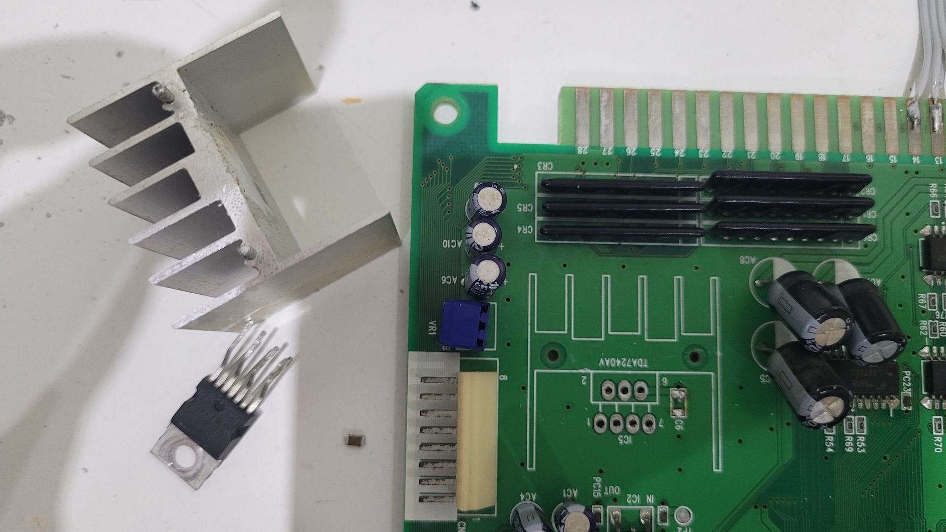
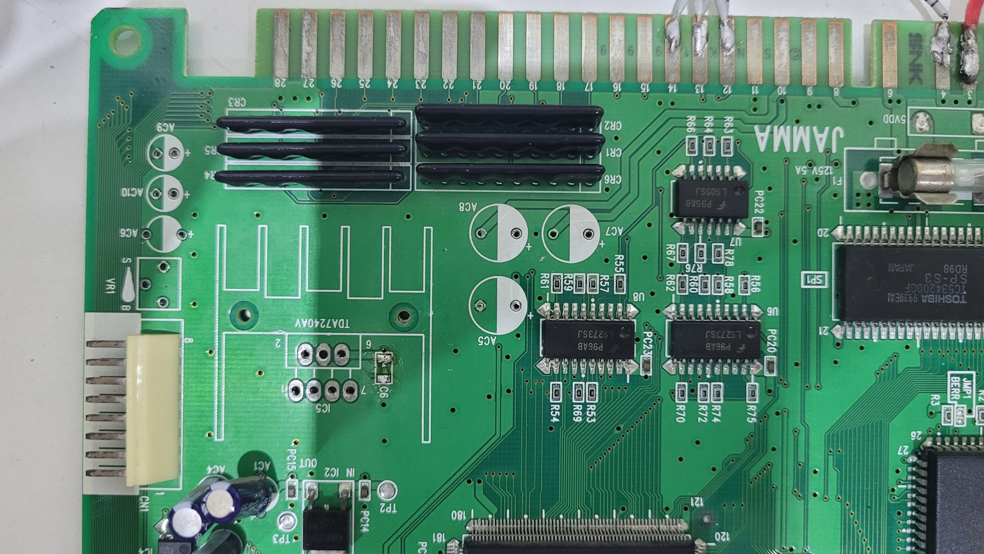
The audio amp and its radiator can be easily desolered
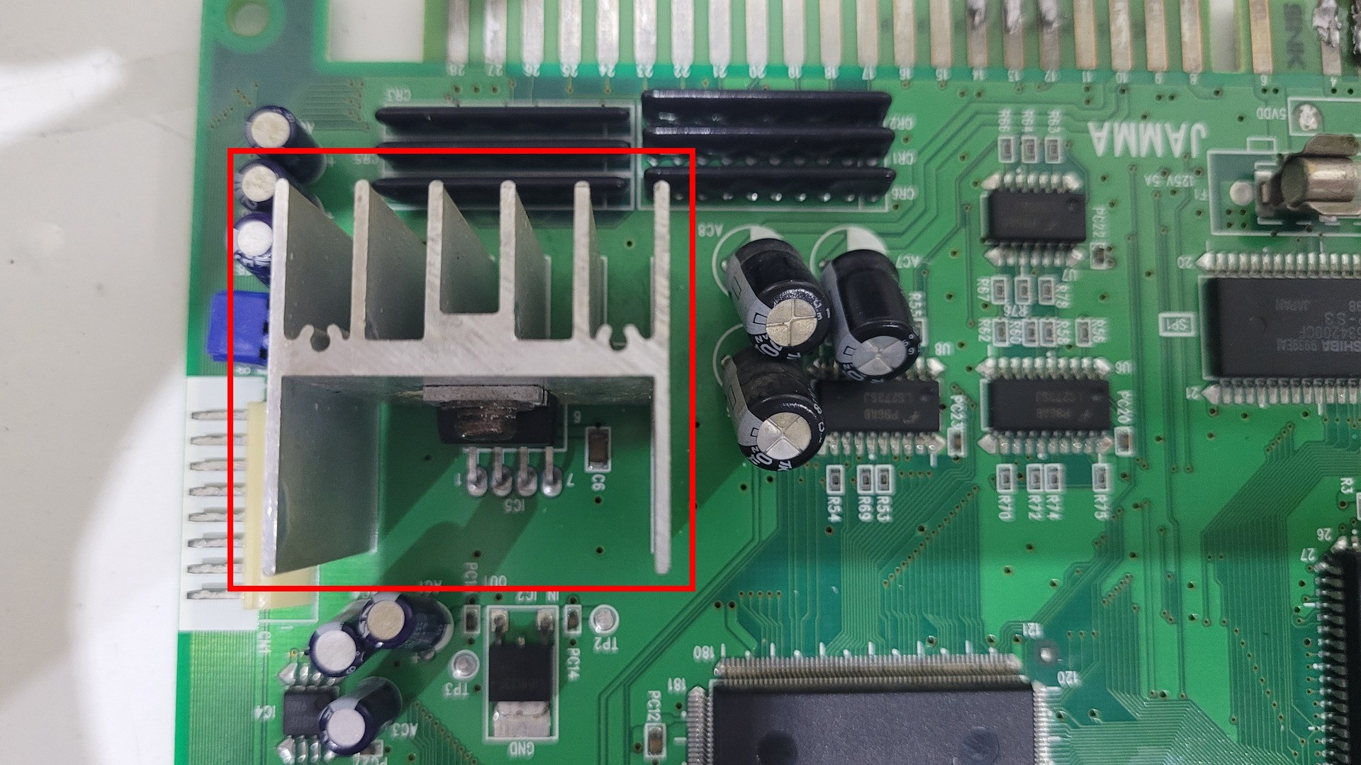
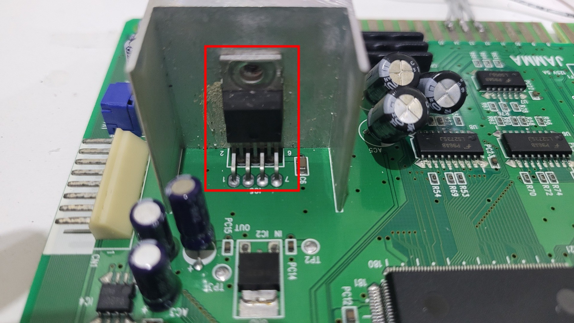
There are also some others components that can be removed : some capacitors and the audio level capacitor
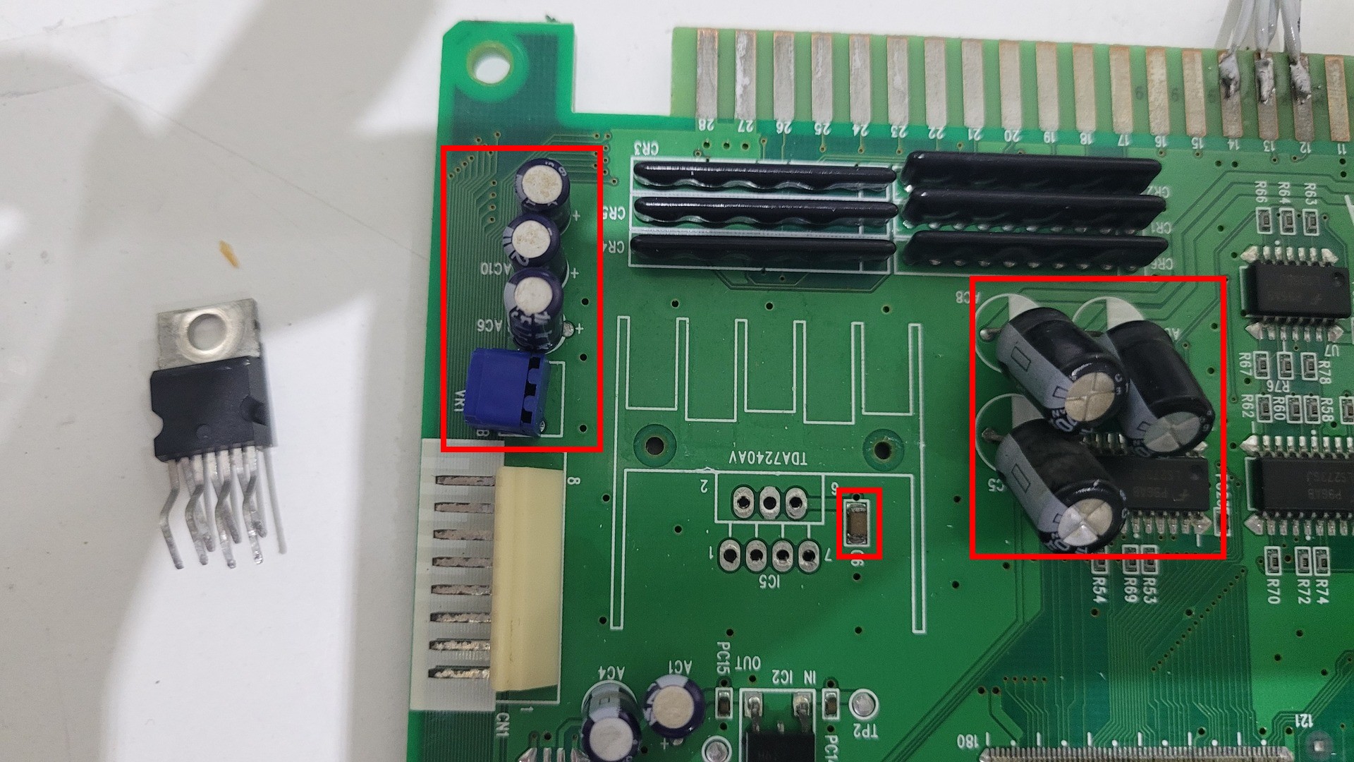
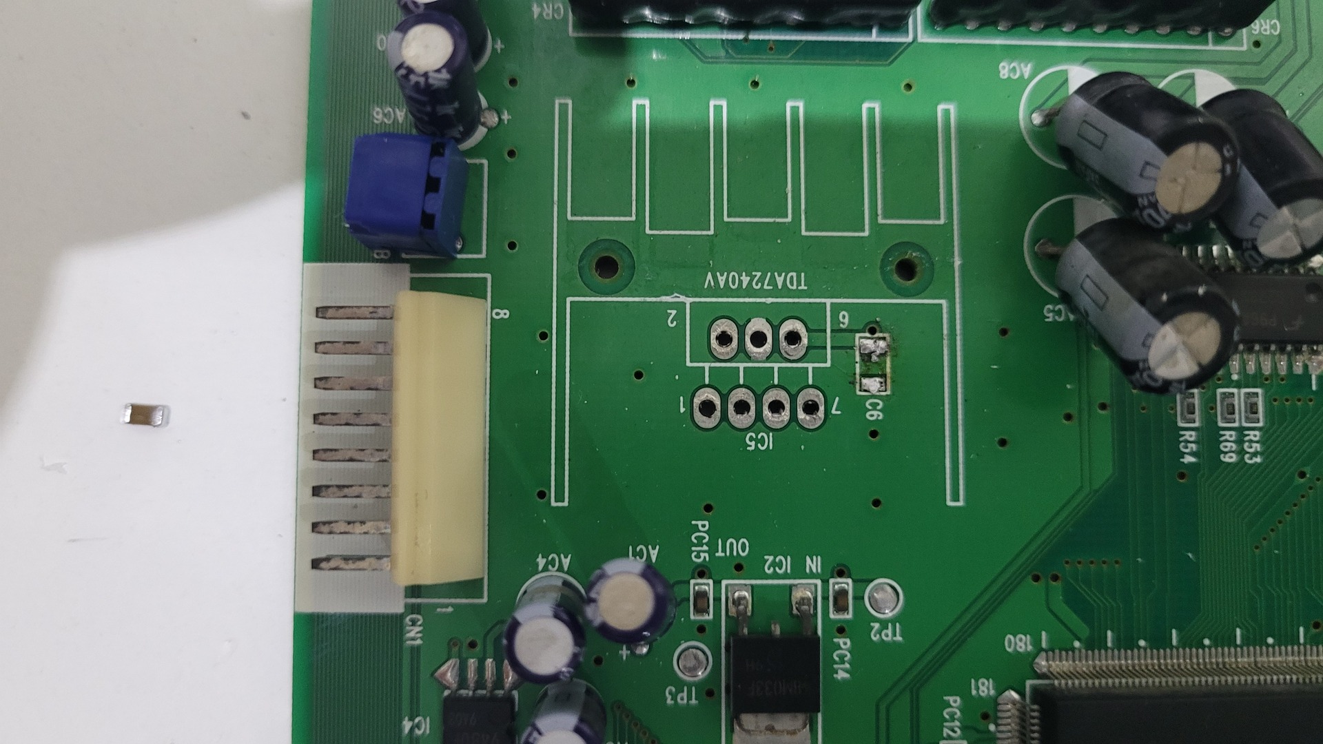
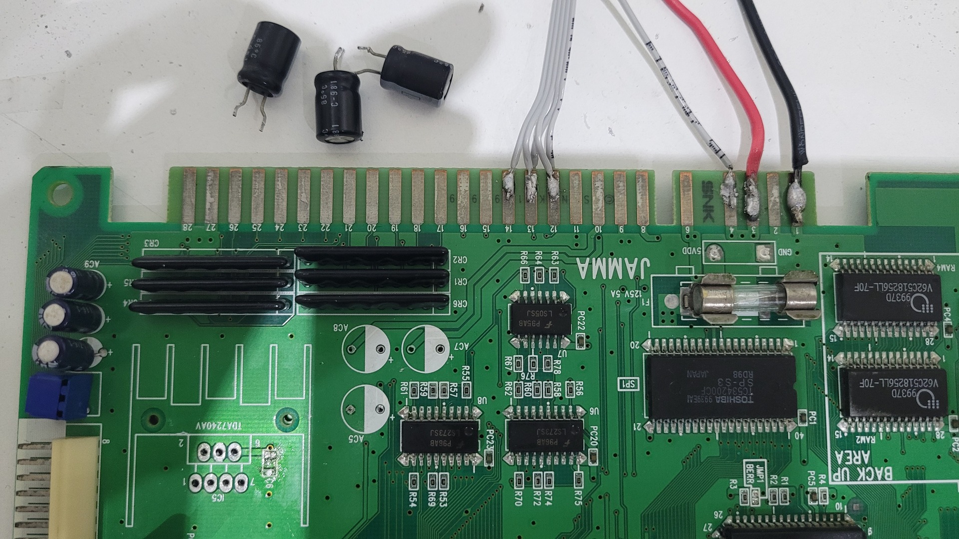
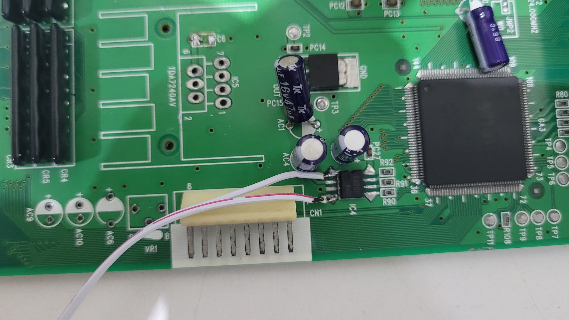
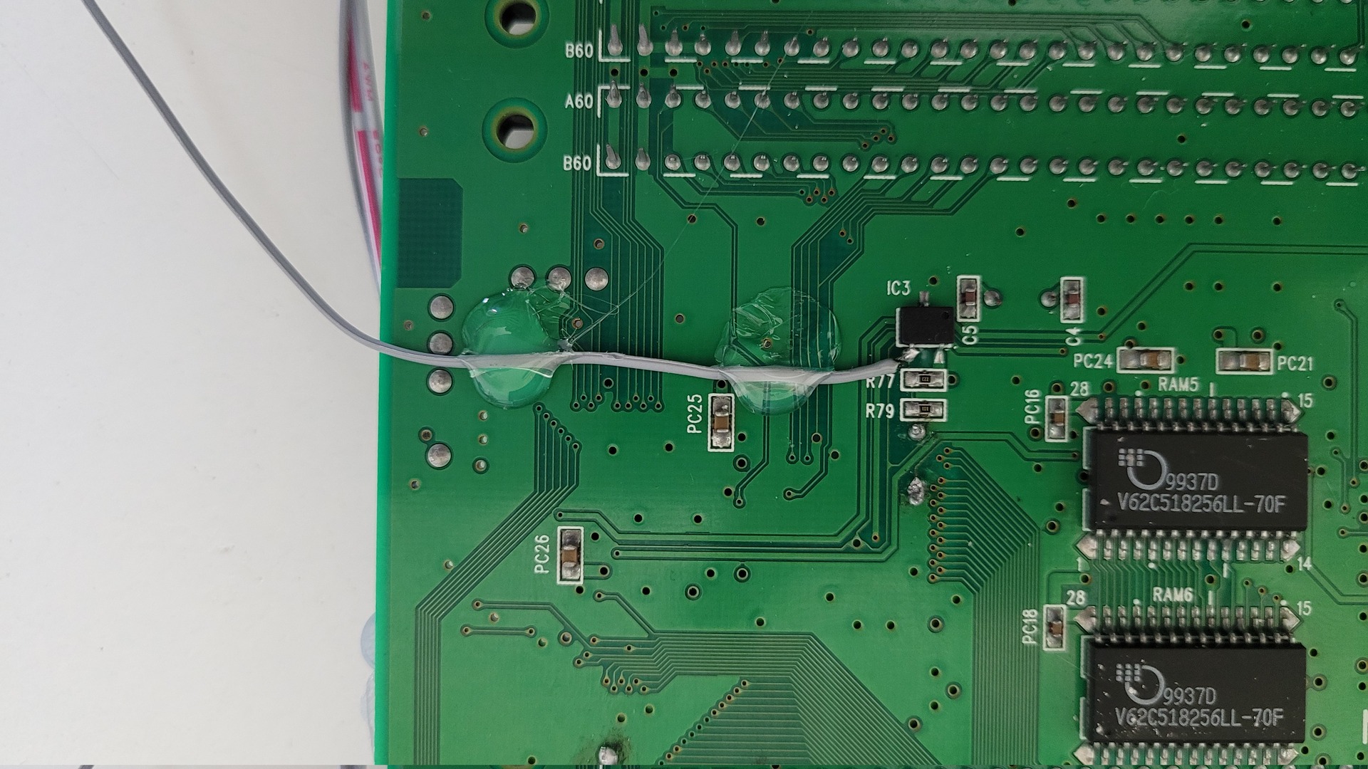
Finaly, we can add some wires to get stereo audio channels. The ground can be took fom the last jama connector pin (28). I used a luster terminal to isolate the wires’ end and make the final assembly easier.

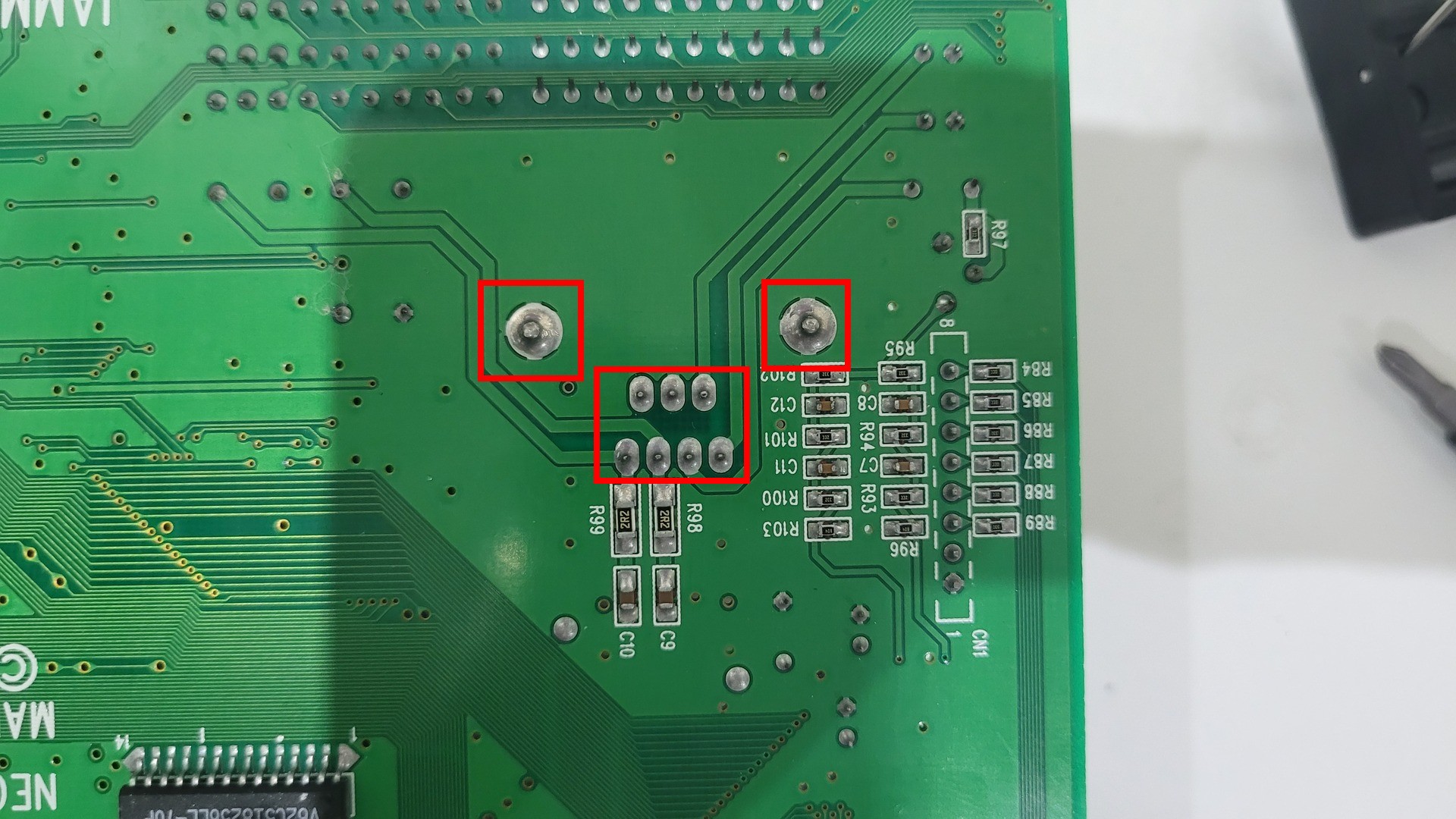
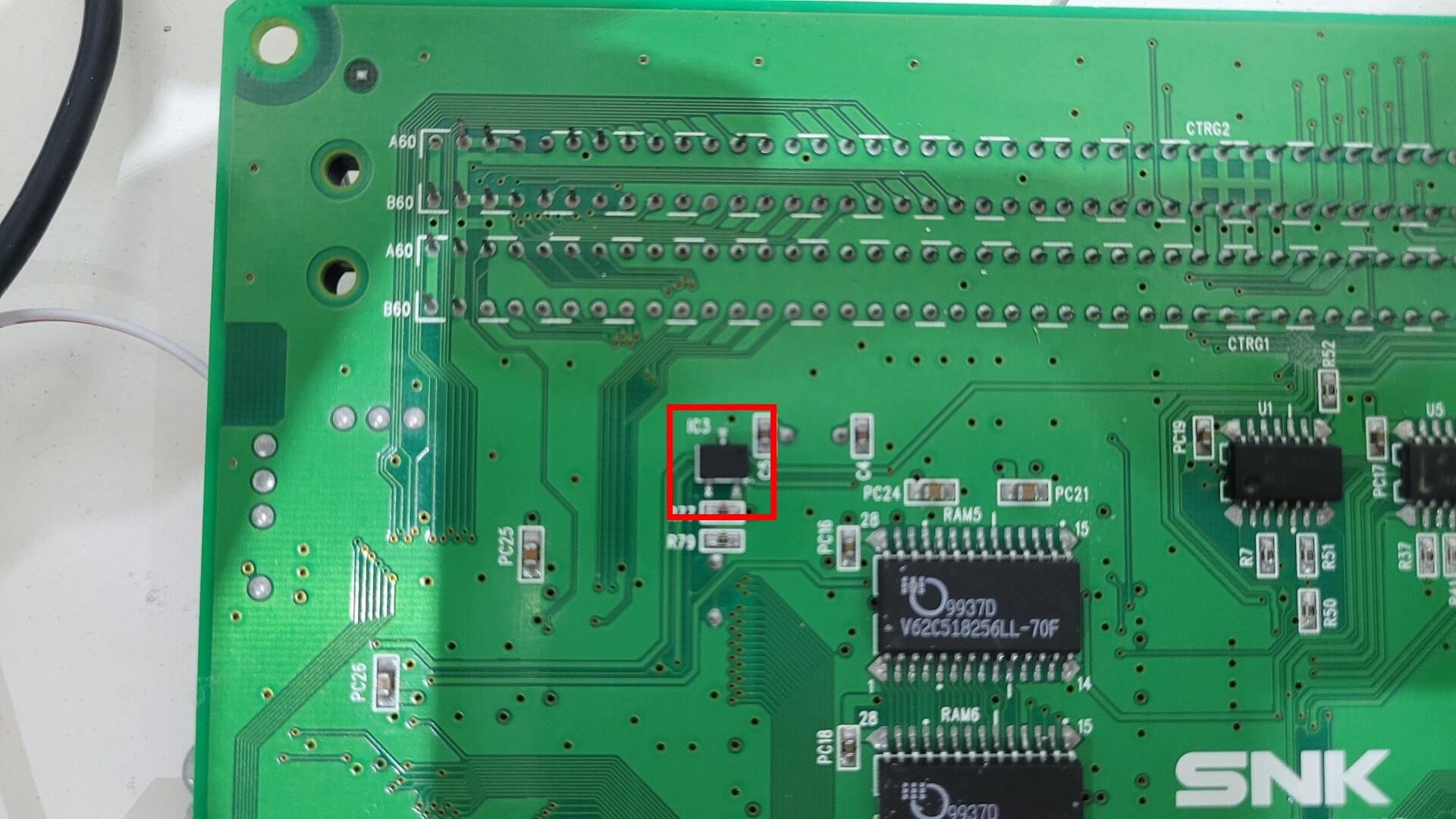
Reset switch
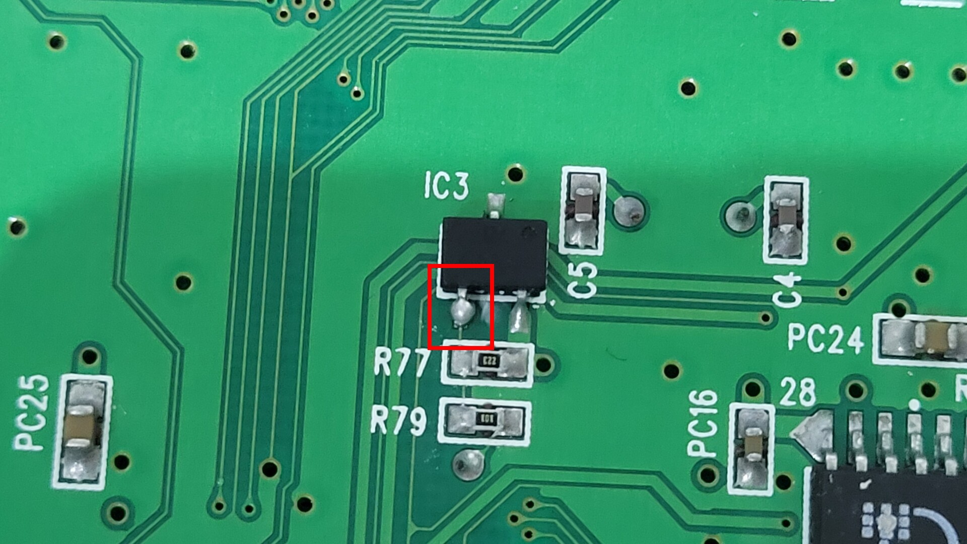
All Neo Geo systems are based on the same logic. So if AES systems have a reset button, the MVS ones can have one too ! The MV-1C use a KIA7045 connected to one of the GPUs. If I understood correctly, this voltage detector pulls the reset signal of the GPU when its power rail voltage becomes low. So to build a safe reset system, you just need to use a momentary switch that connects this rail voltage pin to the ground.
At this point, we just need to attache a wire to the rail voltage pin of the KIA7045, so we will be able to solder it to the reset switch during the final assembly.
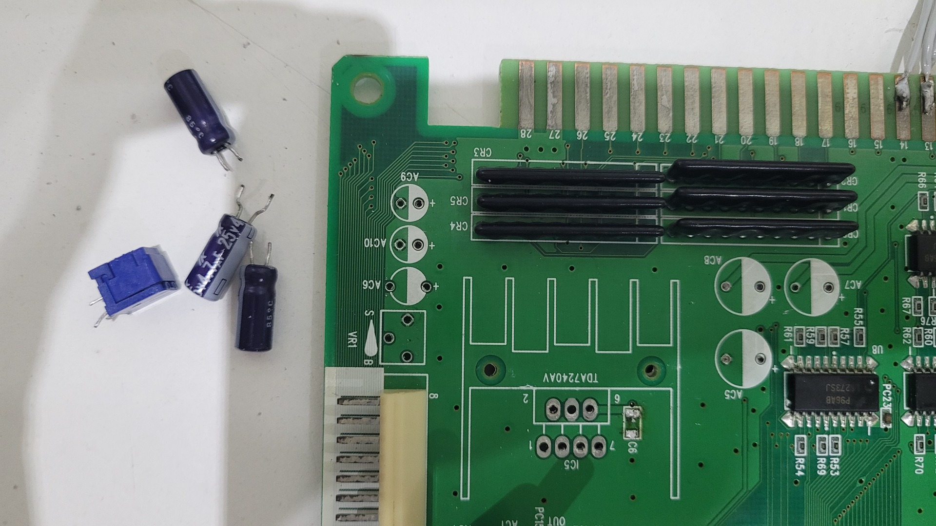
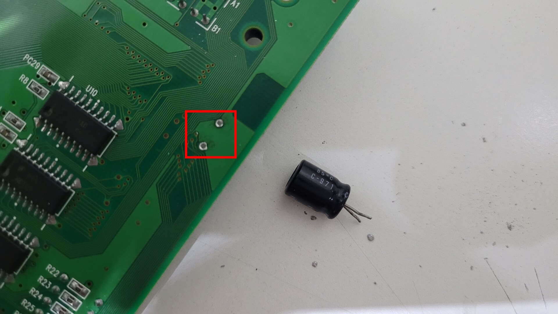
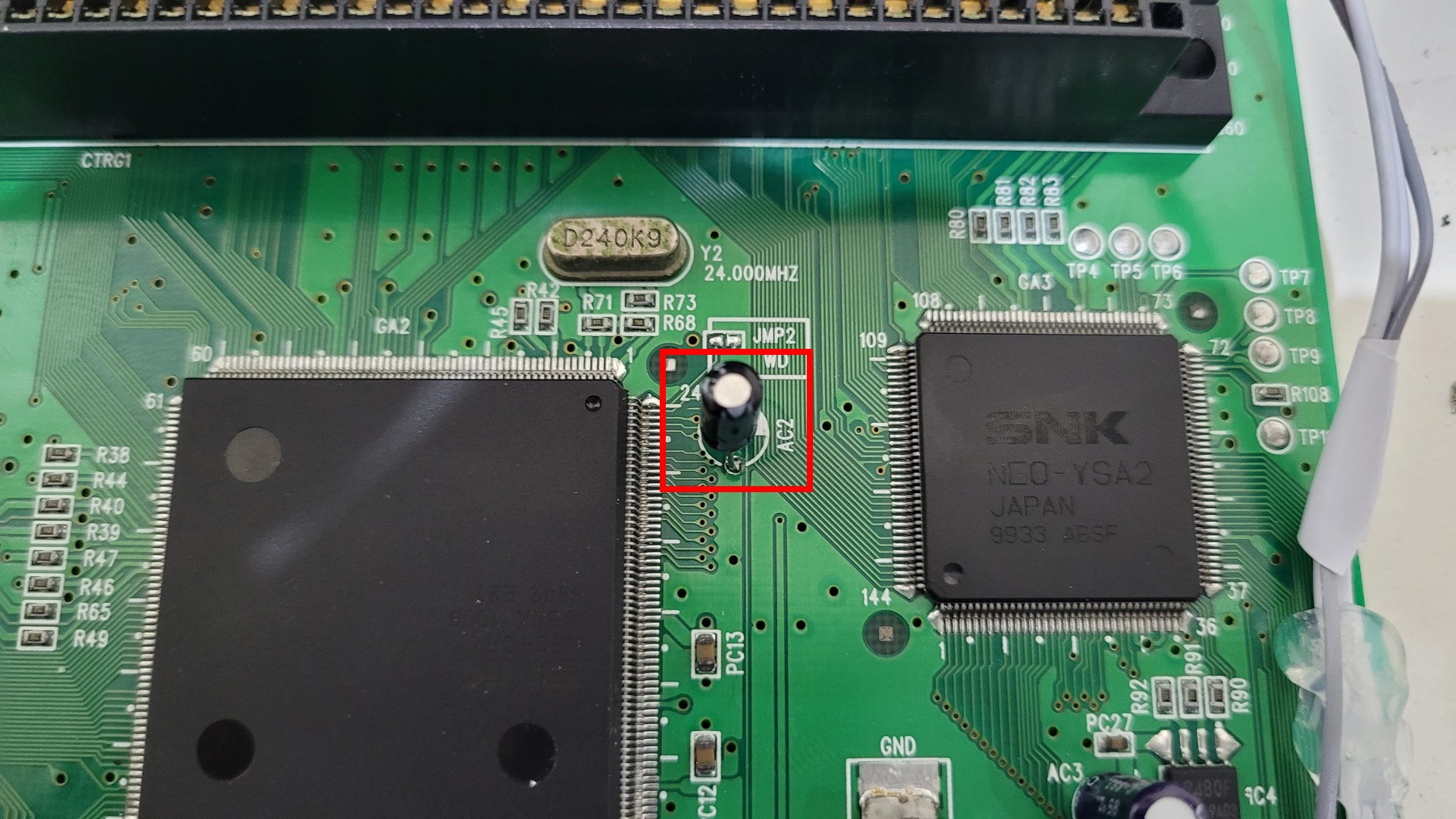
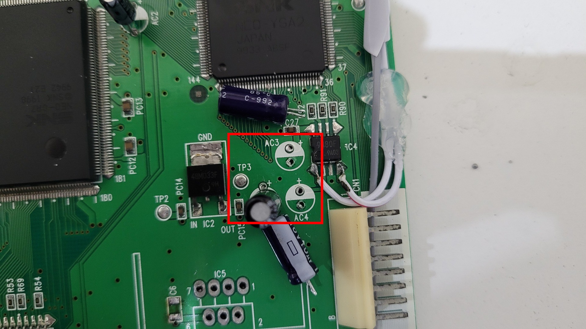
Replacing capacitors
This part is probably optionnal. But I changed all the capacitors to avoid any leak and future damages to the motherboard traces (MVS slots tends cost more and more…). I replaced AC1, AC2, AC3, AC4 and AC11. The values and position of theses capacitors can be found on console5.com
Preparing for Unibios
This part is also optionnal if you can leave with an arcade only experience. But the Unibios makes the console region free and provides AES experience for all games. The installation manual of the Noebiosmasta can be found here : https://www.tsb.space/wp-content/uploads/2018/10/NBMMVSInstall.pdf
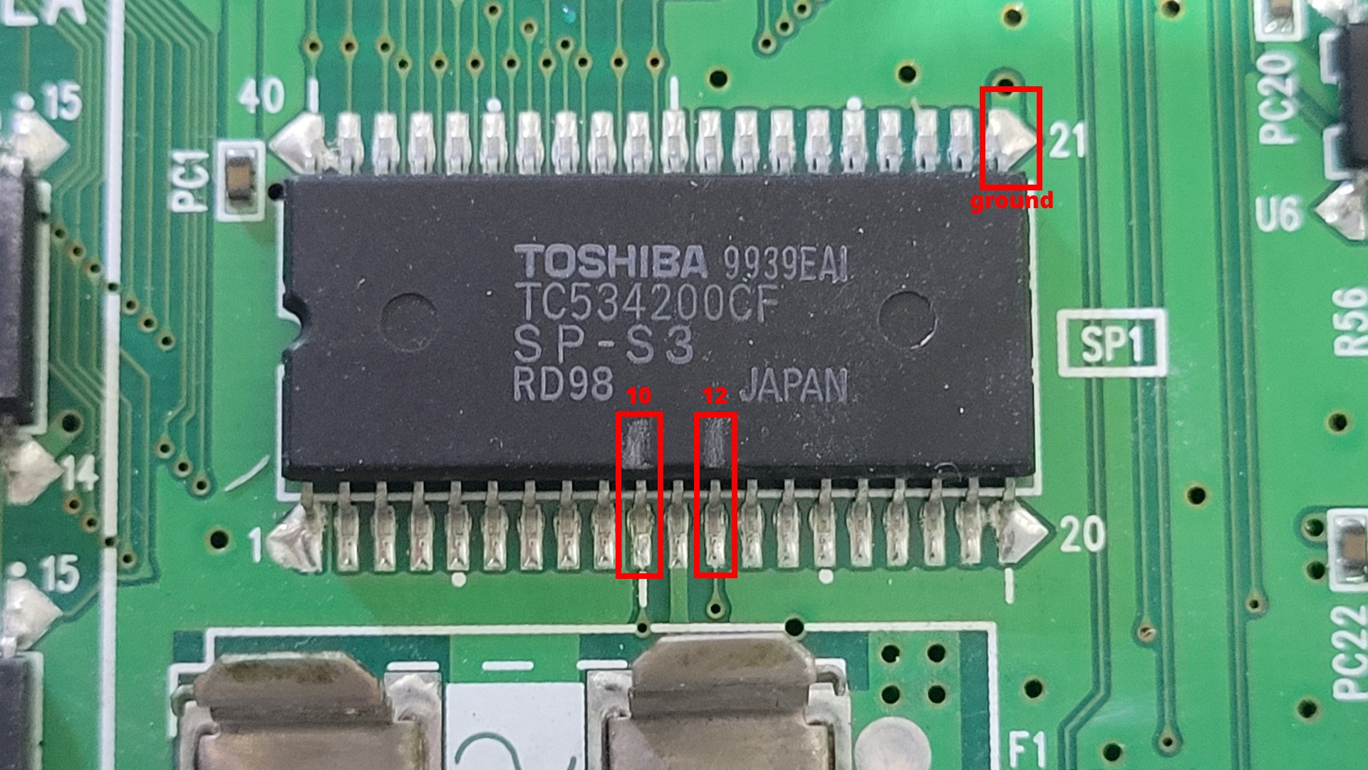
There are two option : either totaly remove the original bios and get the needed signals from the motherboard, or lift up thoses two pins and disable the original bios by putting pin 10 to ground. I personnaly took the option to keep the orignal bios, because it was easier to test all my mod before inserting the new bios. Also because removing the bios could be destructive for the chip and I might use this board in another project in the future.
I first marked the pins 10 and 12 before starting, then I lifted the pins, soldered 2 wires, secured them with hot glue and finaly wired pin 10 of the bios to ground
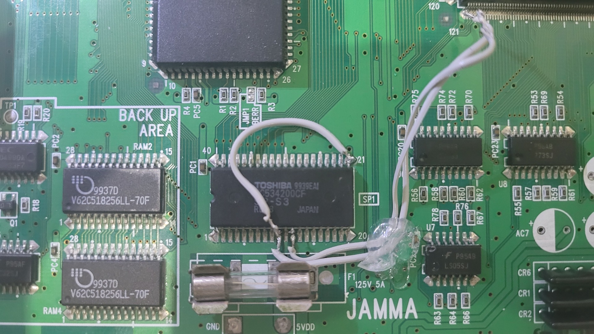
I did not plugged the Unibios socket to the CPU immediately because the motherboard was easier to manipulate on a table without it.
Controllers ports
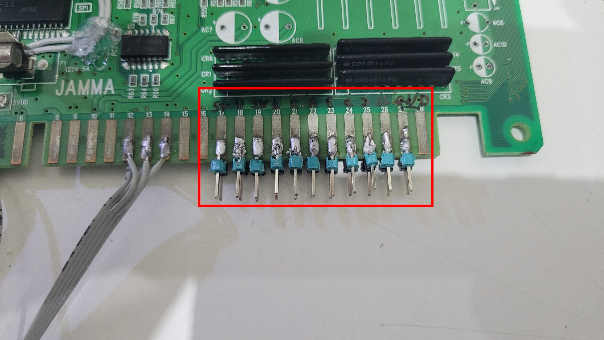
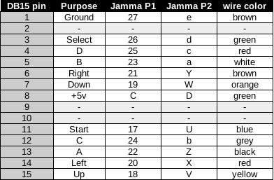
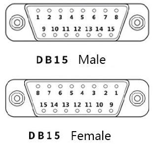
The way the Neo Geo handle controllers show the beauty of simplicity : one wire / connector per button. This makes it easy to wire the DB15 connectors. I chose not to solder the connectors directly ont he jama connector. Instead, I soldered header pins to the connectors could be tested and replaced with ease.
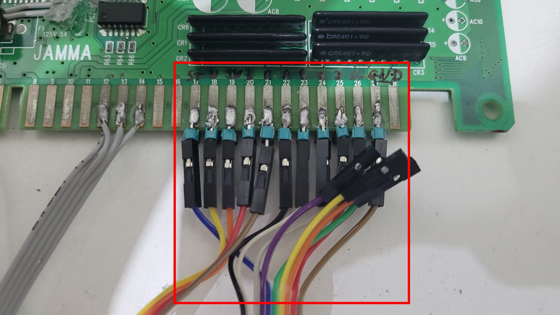
And here is the wiring diagram for the two DB15 connectors. Note that one line is +5v and should you check twice to avoid any damage on your expensive Neo Geo controllers.
AV and power wiring
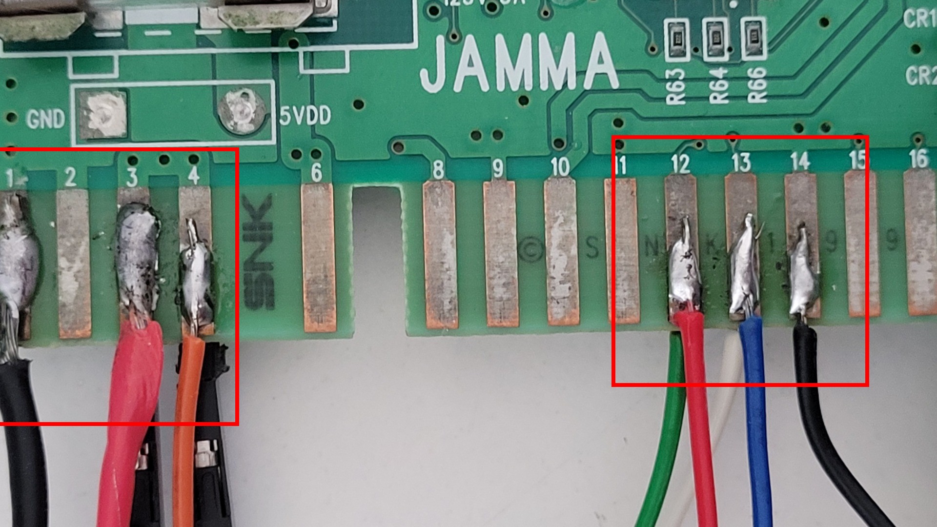
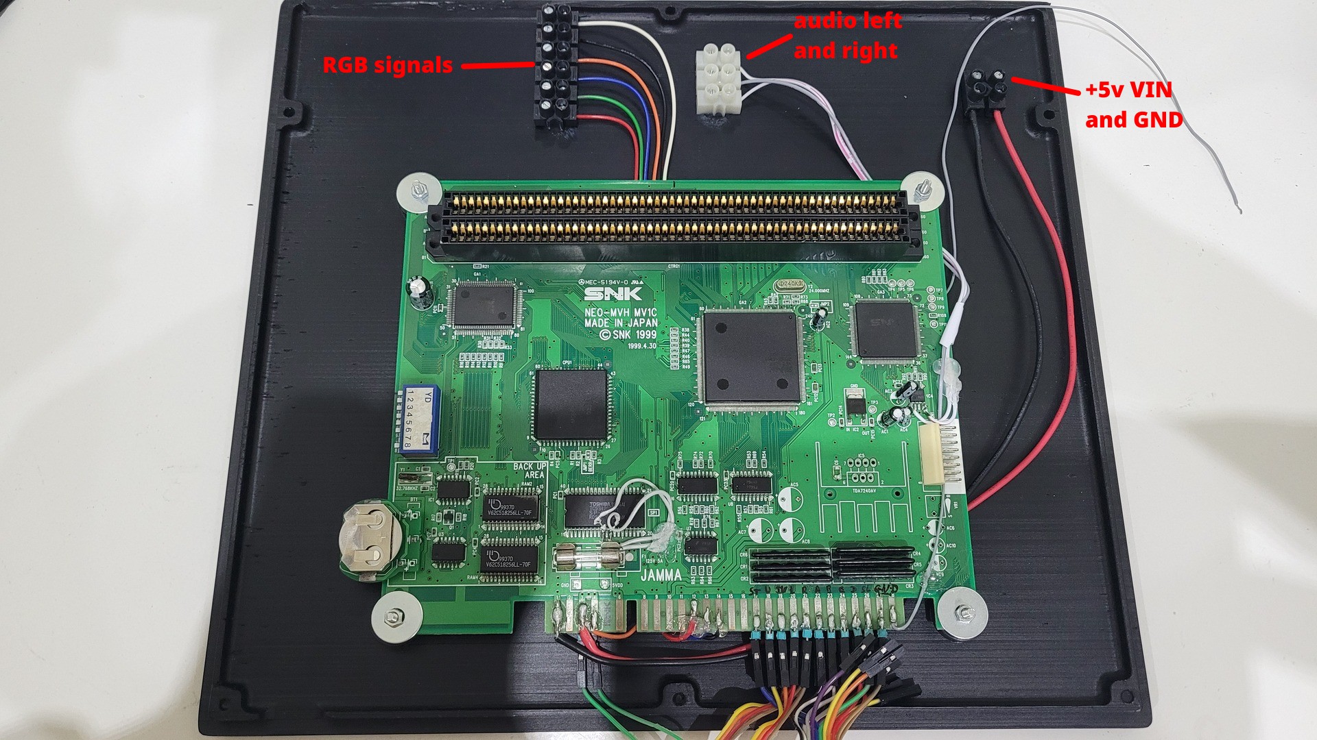
Still in the concept that simple is beautifull, the Jamma connector provides all RGB signals for a 15 Khz compatible screend. More over, as we removed the audio amp, the board can be powered with 5V. I chose the pin 3 for +5v in and pin 1 for power supply ground.
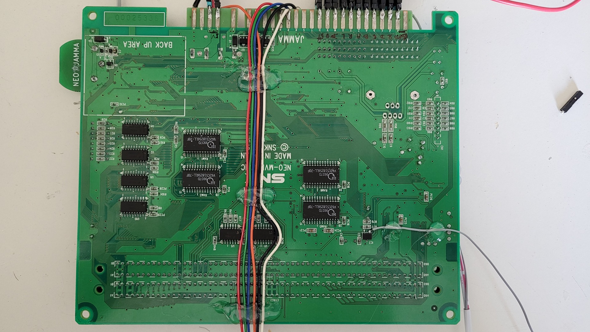
The video wires are passed on the bottom of the motherboard and fixed with hot glue. This is needed as I mounted the board with the jamma connector in the front of the console, whereas the video connector is on the back of the case.
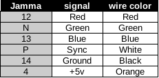
Here are video signal wiring table I used:
AV connector
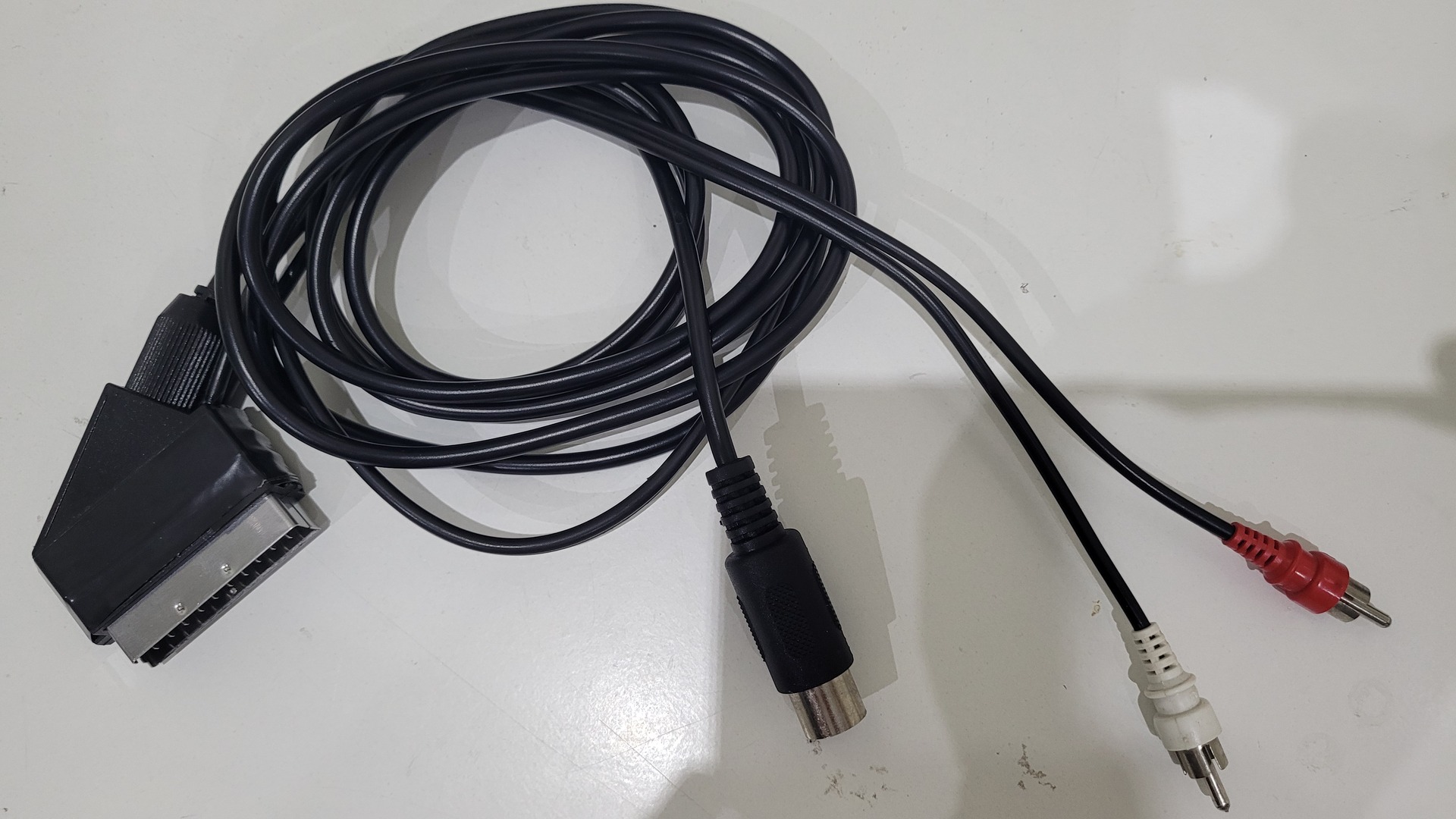
I used a 8 pins DIN connector with C shape (also known as 270°) for video output. This is the same connector as the Sega Megadrive 1. I chose such a connector because Megadrive cables are easy to find and really cheap.
As the 3d printable shell I found povides holes for 2 audio cinch connectors, I decided not to output audio throught the video out connector. There is two advantages doing this way : the sound output can be plugged to some hi-fi equipement and this allows to get stereo sound whereas the Megadrive cable has only 1 wire for mono sound output.
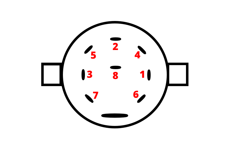
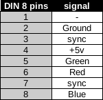
Here are how to wire the connector. 2 important things to note:
- The sync signal is wired to both pin 3 and 7 so the connector should be compatible with Megadrive (sync on composite) and AES (composite sync) cables
- A 0.1uf ceramic capacitor between sync and ground enhance de compatibility with recent LCD / OLED TV, because the NeoGeo sync signal is slighly off the standard. It is fine for old CRTs, but not for all modern displays
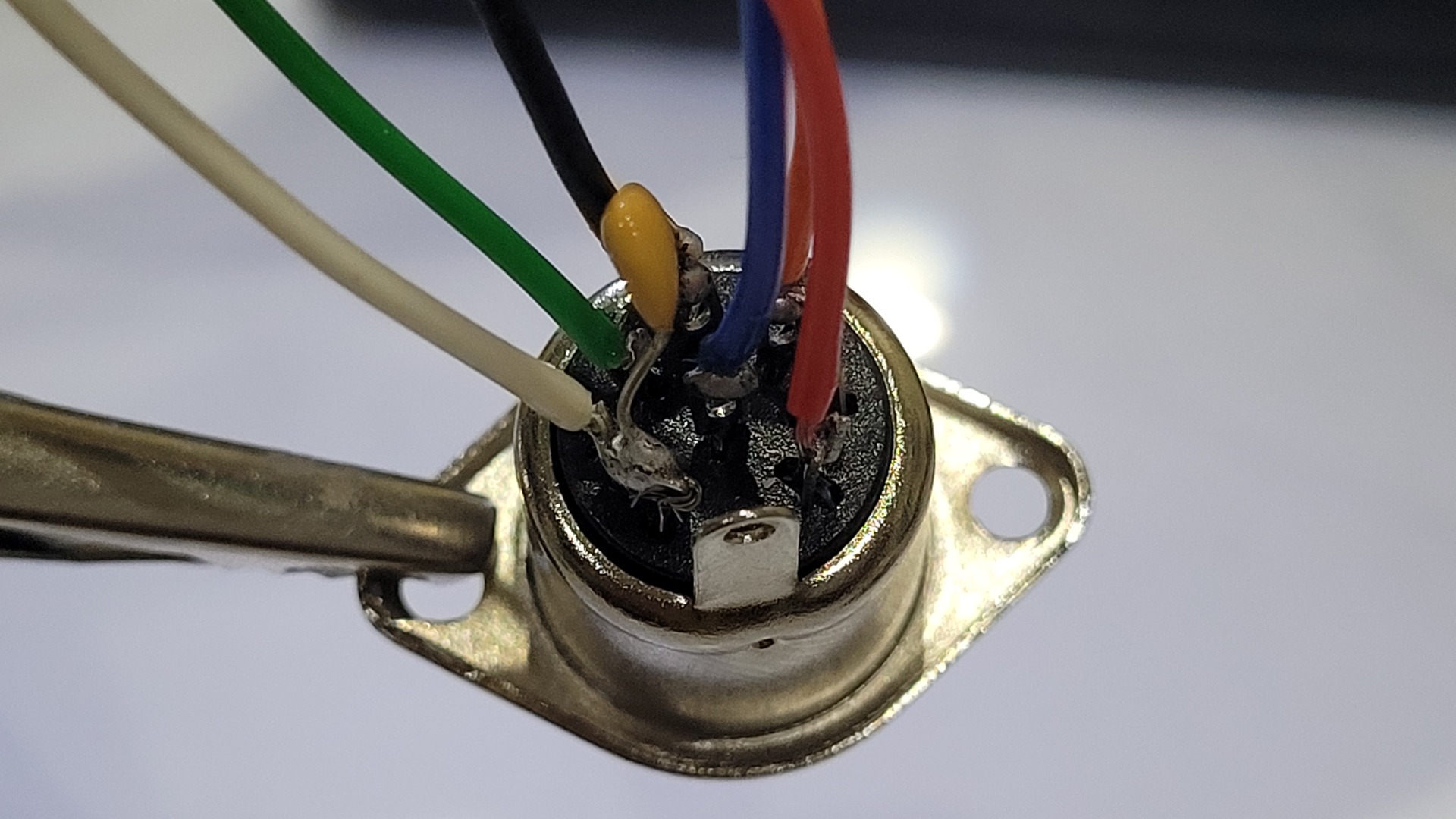
Below are a schema of the back of the connector, a wiring table and the real connector
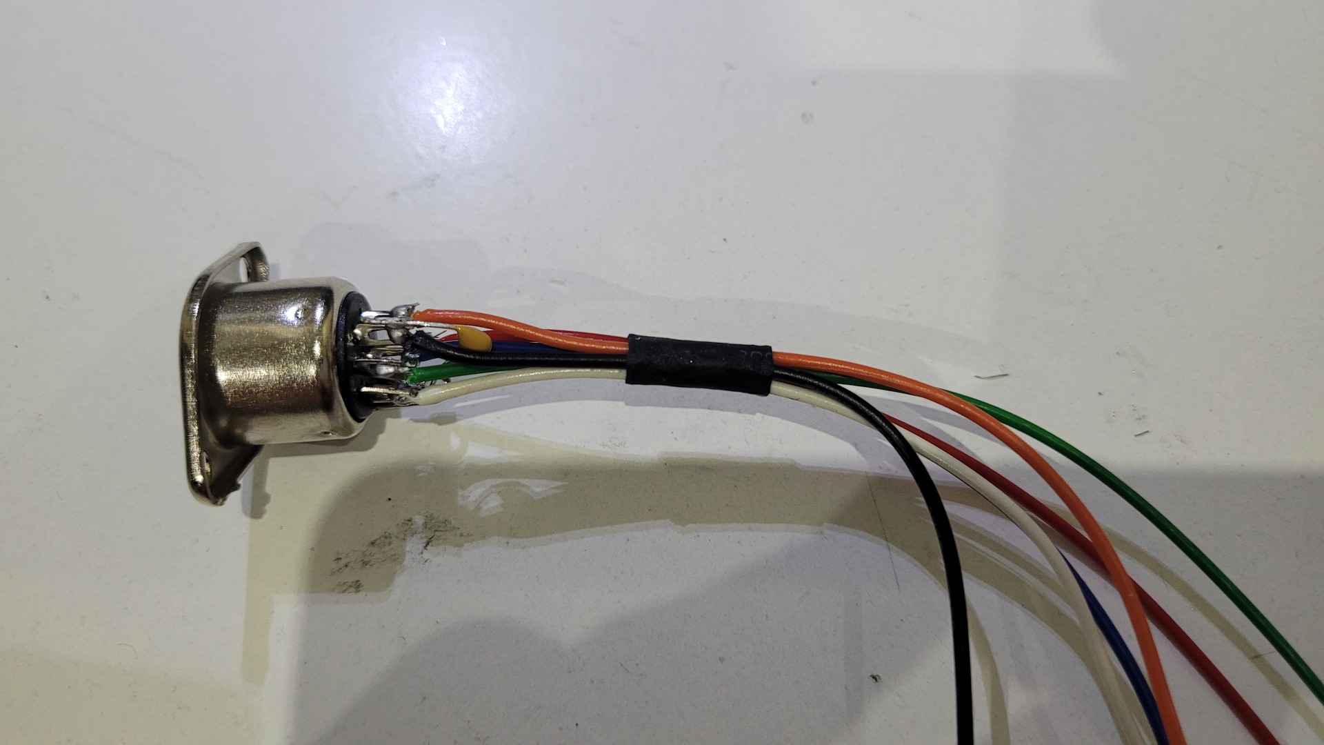
AV Cable
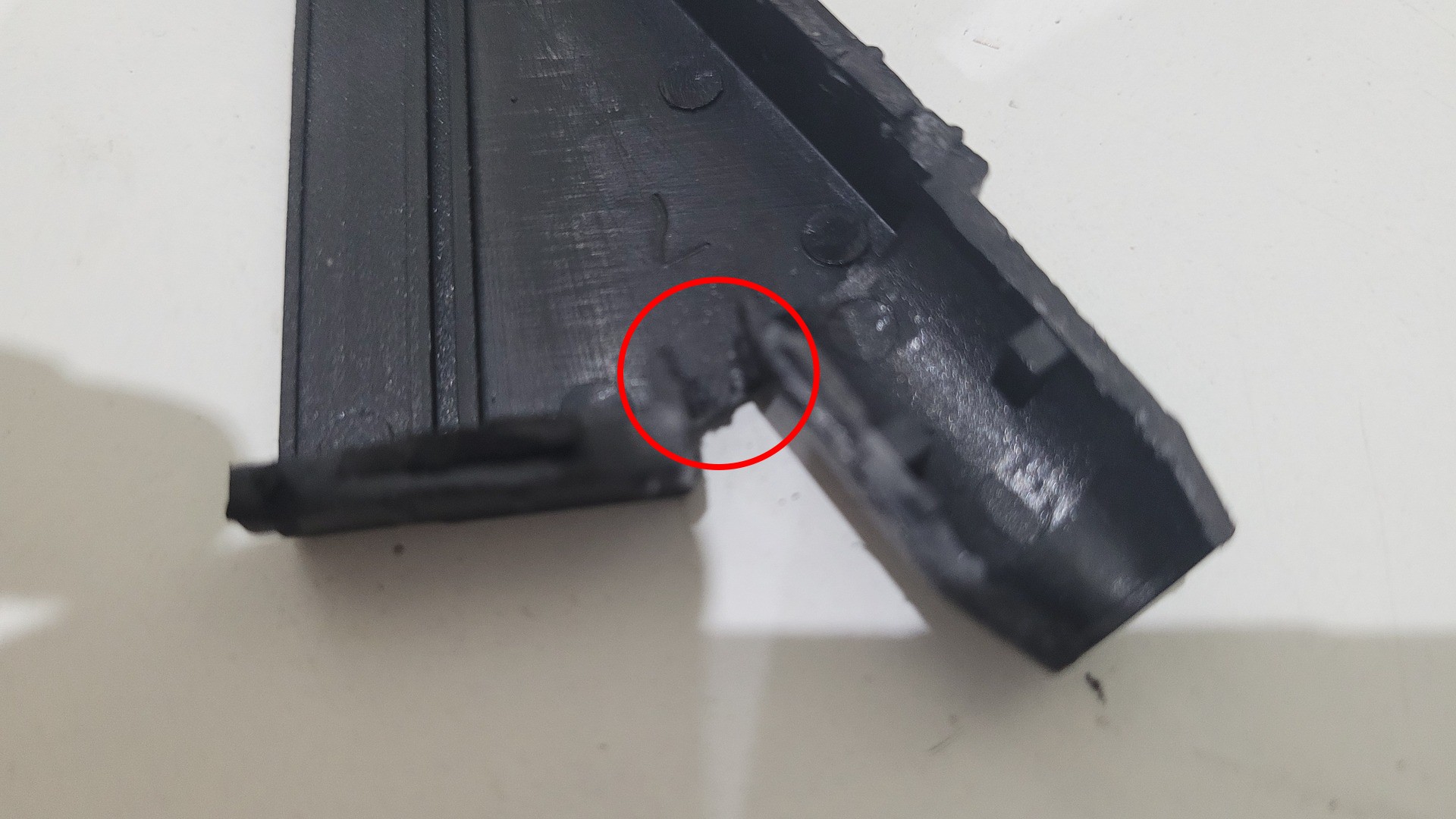
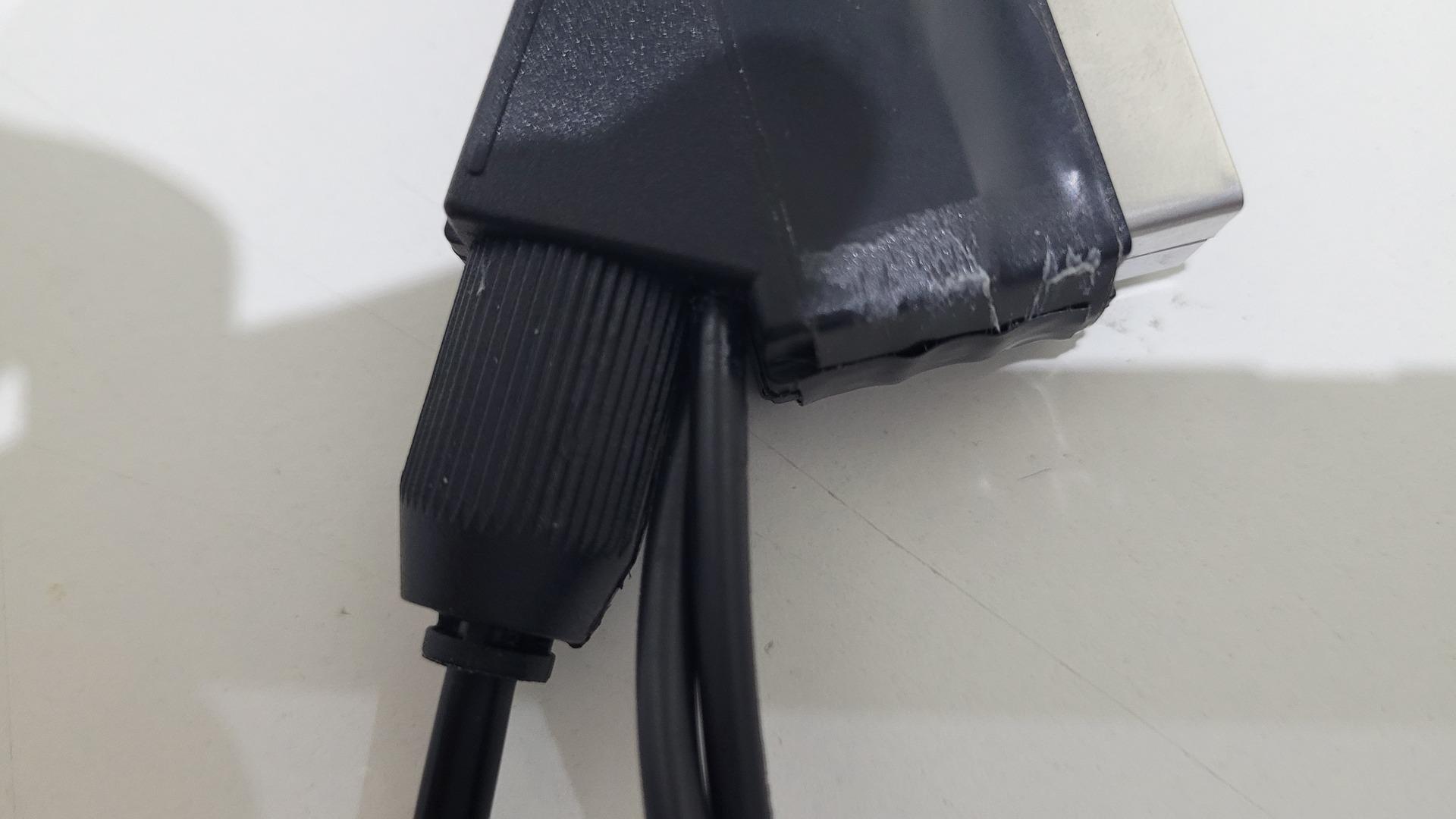
As I mentioned earlier, I used a Megadrive 1 cable. I opened the scart connector, cut the original audio wires and solered news audio cables with cinch connectors on the other side
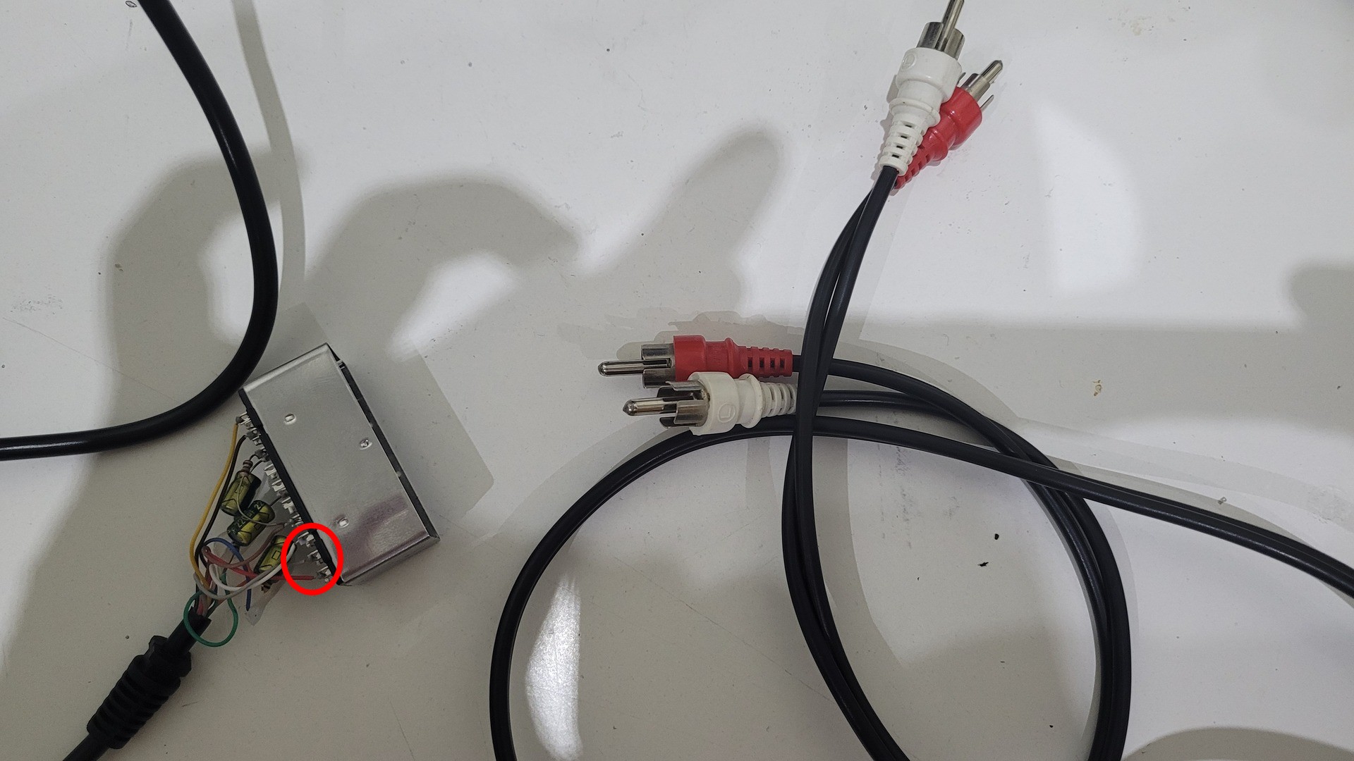
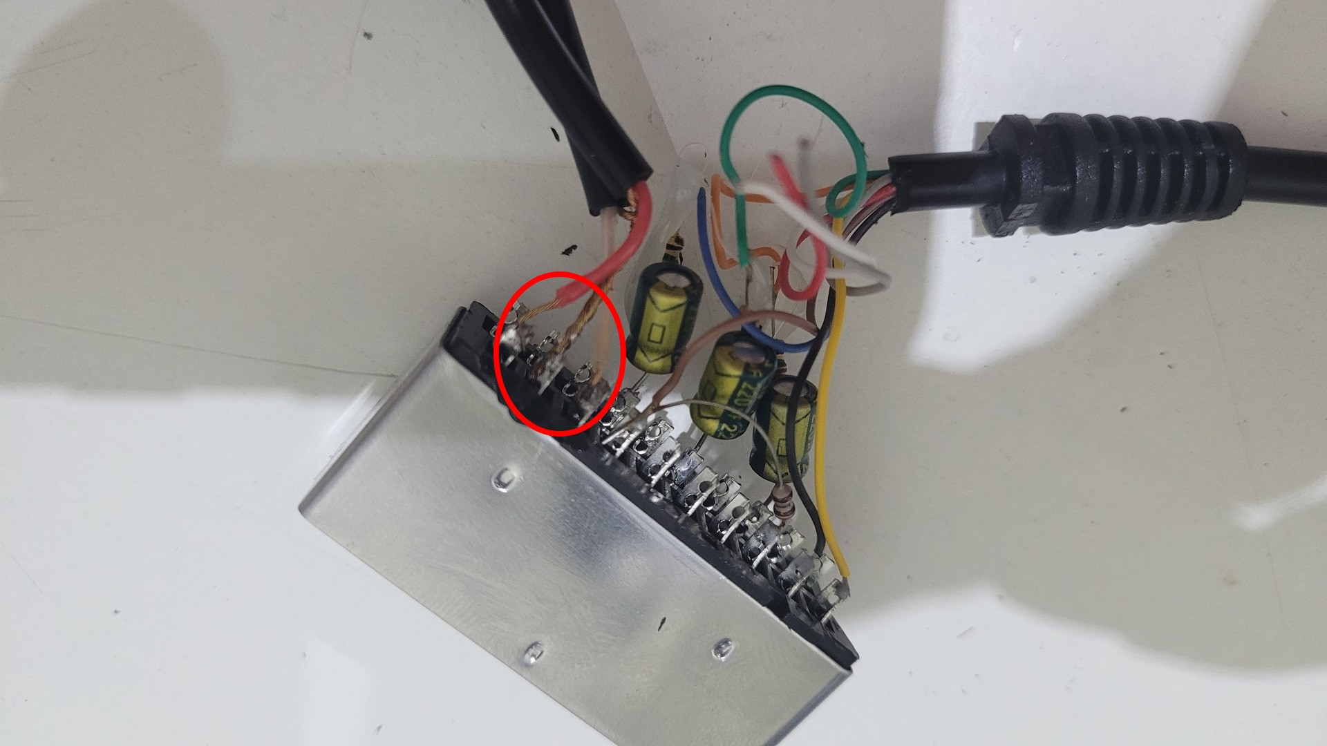
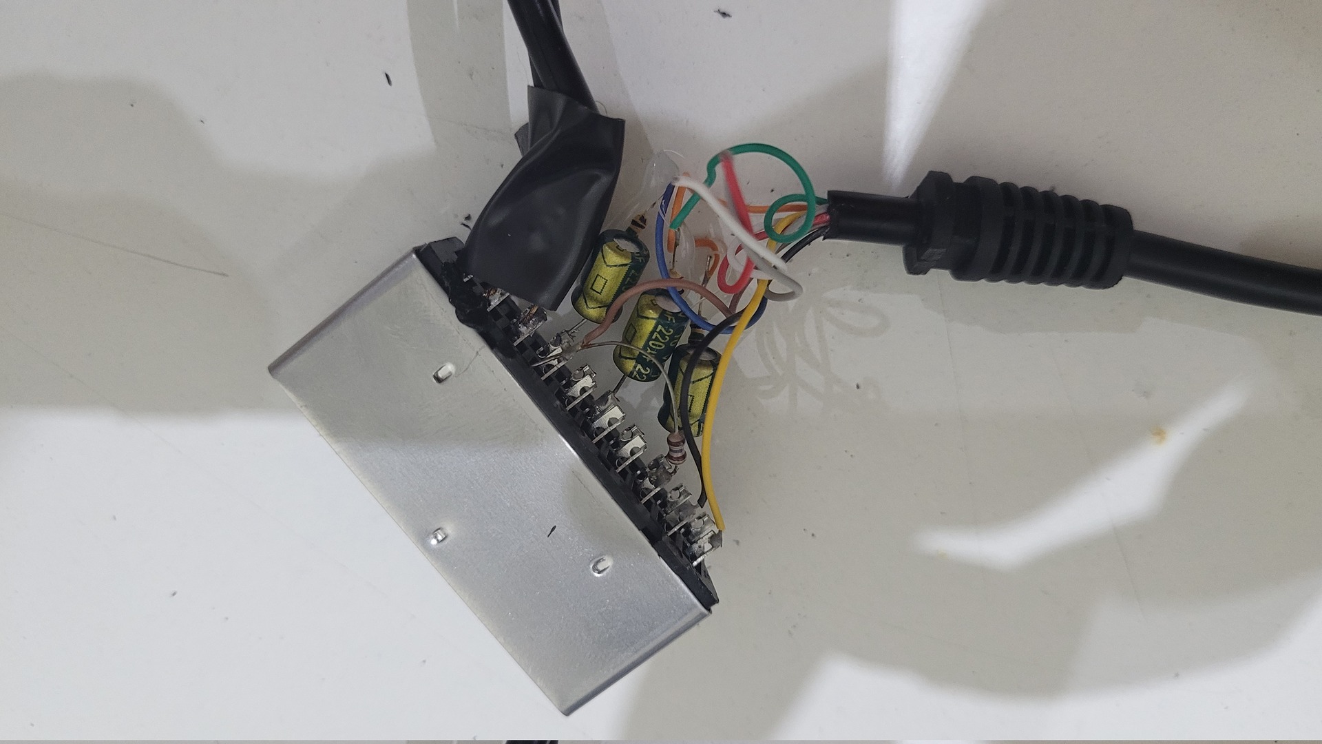
In order to fit the audio cable, I had to cut a side of the scart enclosure
Preparing the case
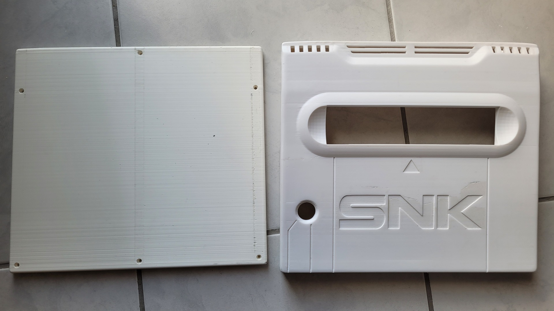
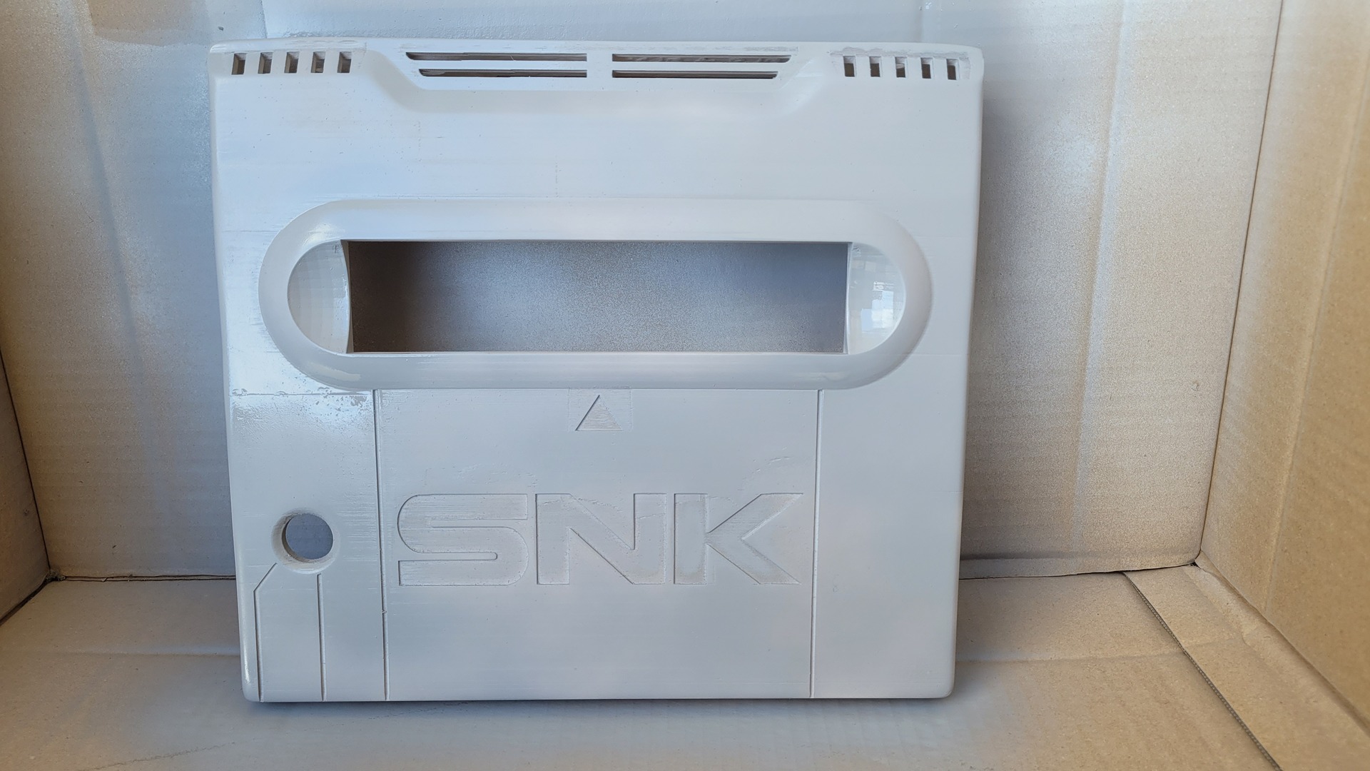
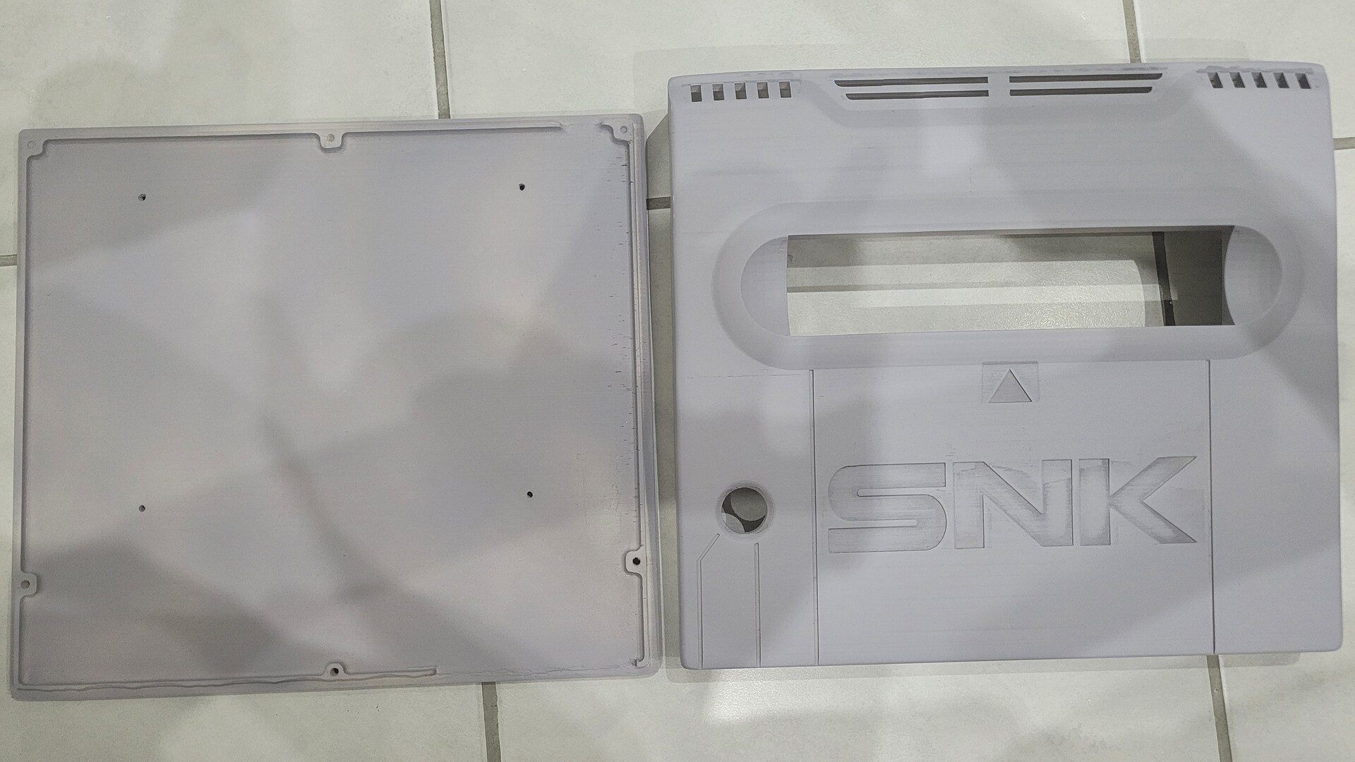
3d printed parts
The console shell as been printed from a beauttifull model on thingiverse : https://www.thingiverse.com/thing:4166610
The model is quite big and your printed must be able to print this dimensions : 27x30cm.
I printed the top and bigger part in ABS as it is more robust, and the bottom has been printed in PLA.
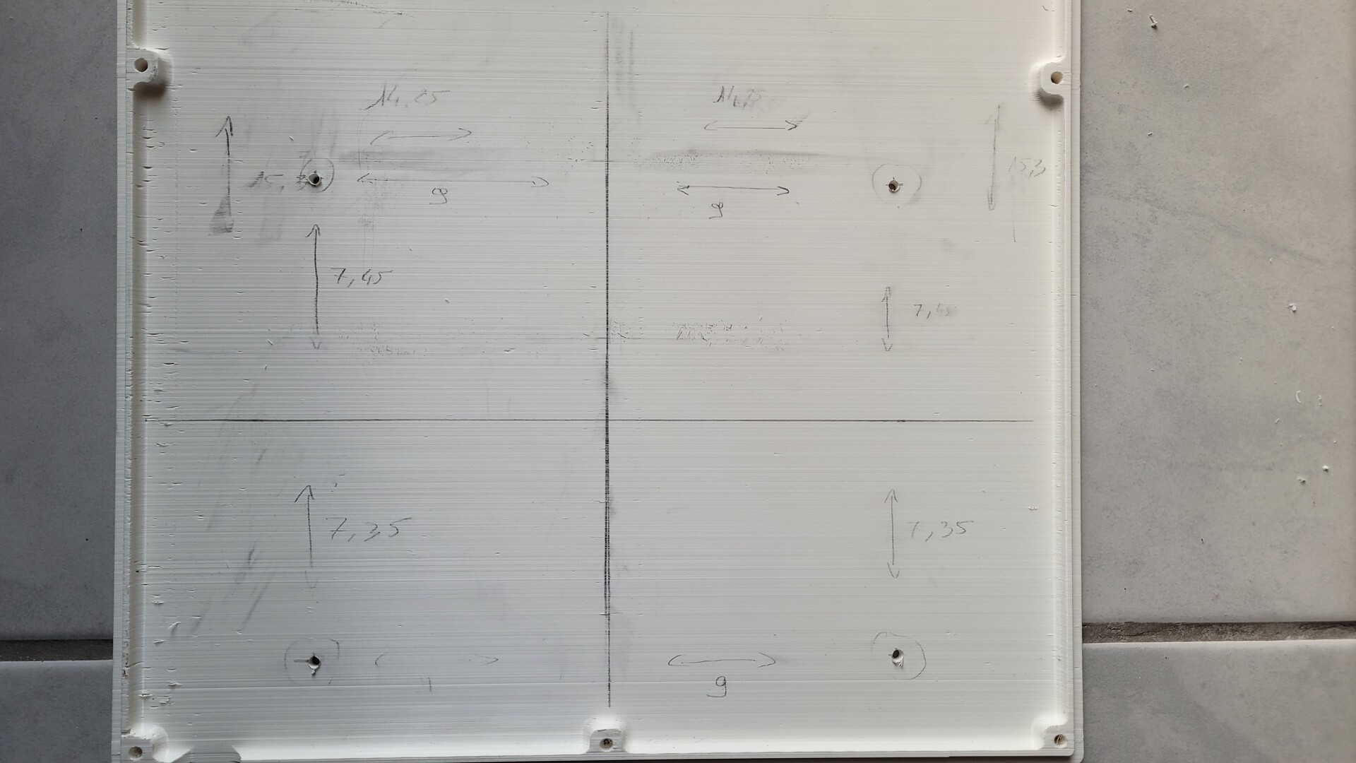
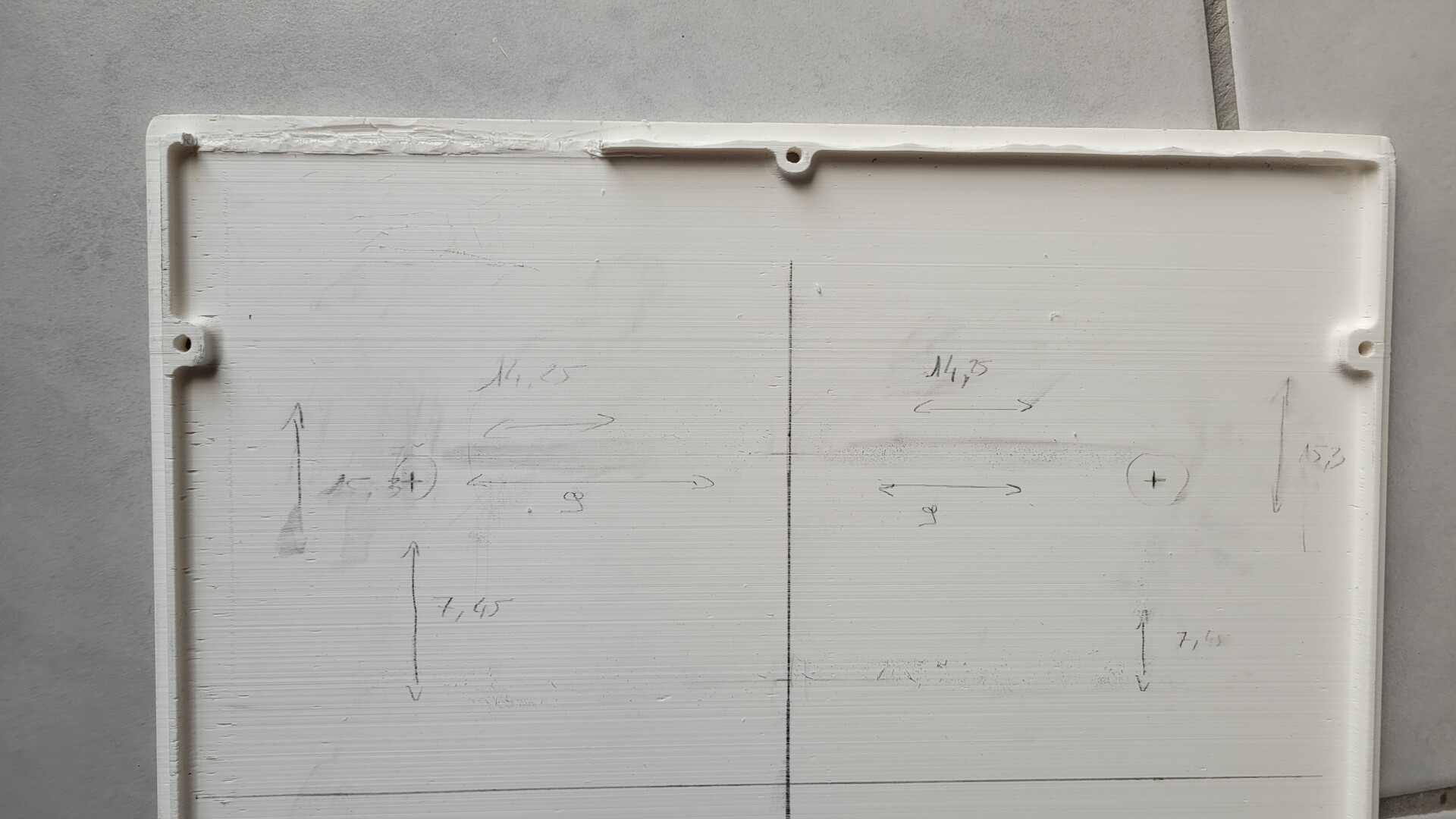
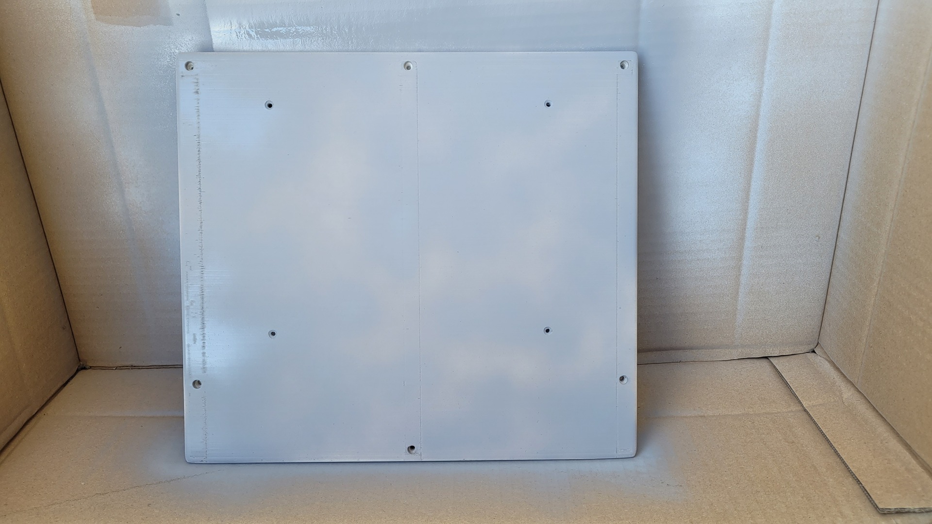
The bottom of the shell does not have any hole to fix the MVS motherboard. Here is the schema with the dimentions I used :
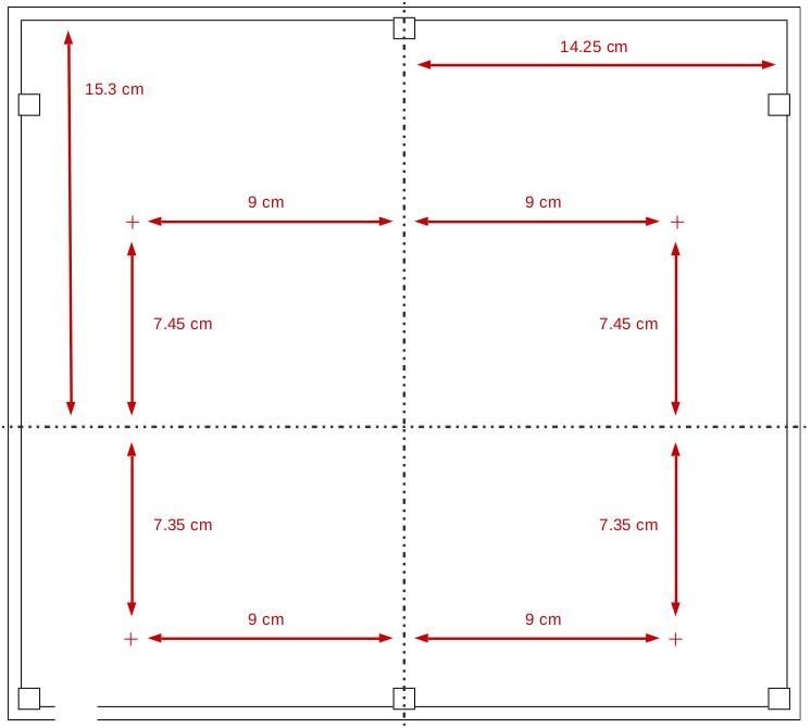
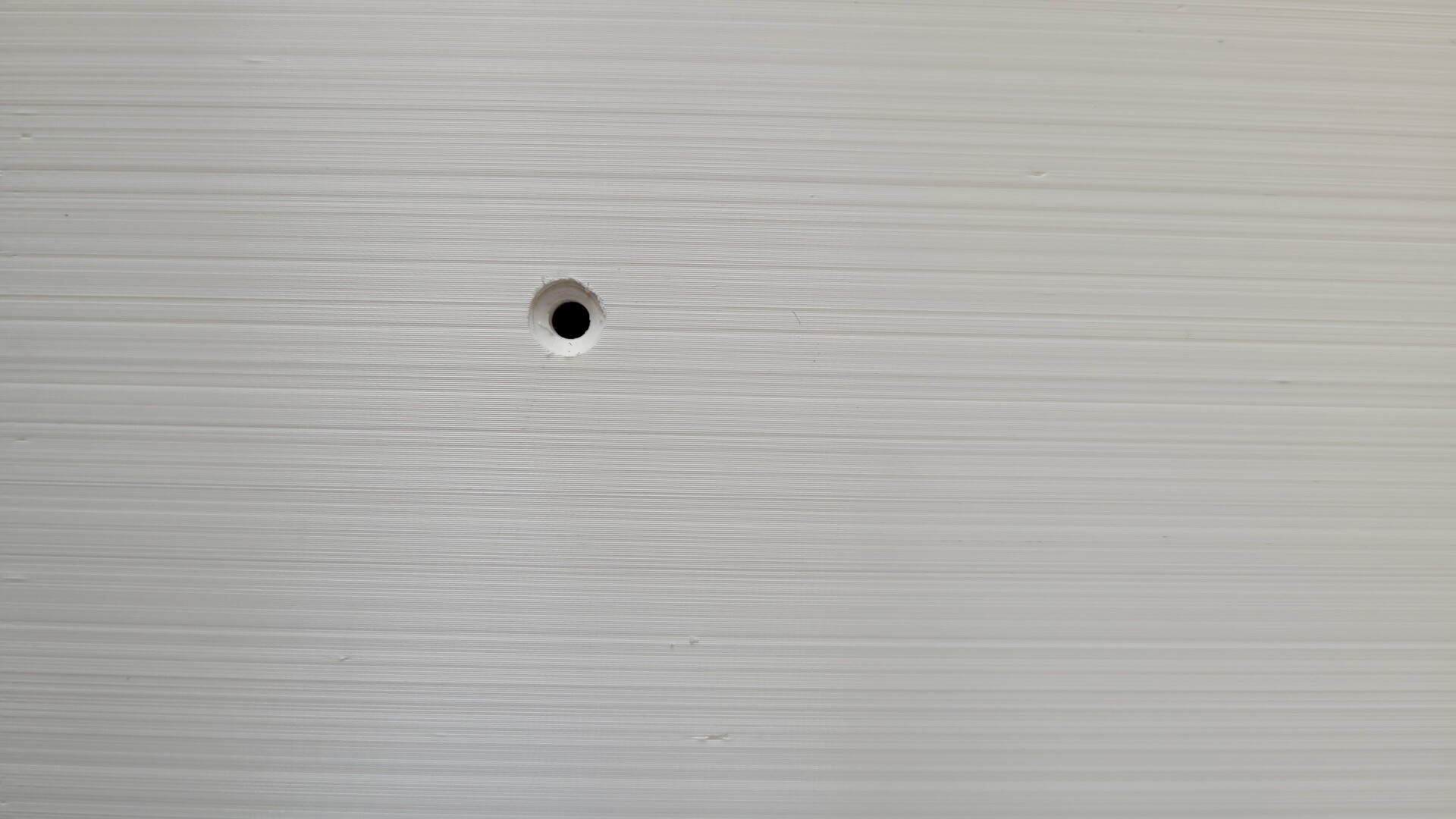
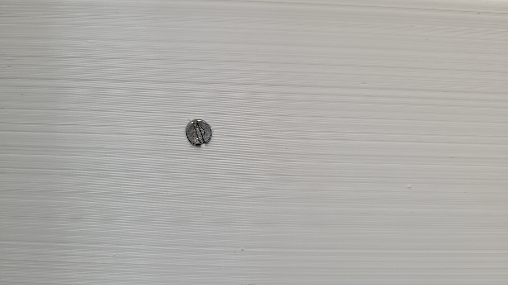
I drilled 3mm holes, and I used a 5mm drill bit to enlarge them so the screw heads are perfectly flat with the bottom of the shell
Last modification : I had to remove the border in the video and audio connectors zone in order to fit correctly the top of the shell
Paint job
Before painting, I sanded all the sides of each part, starting with P600 and finishing with P1200.
Applying the primer :
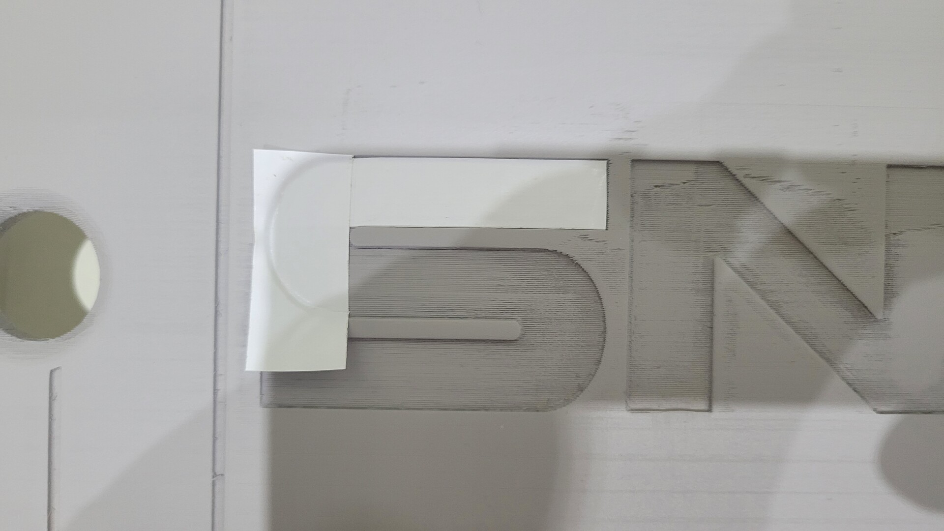
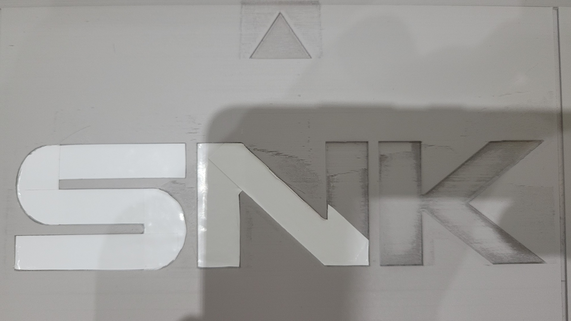
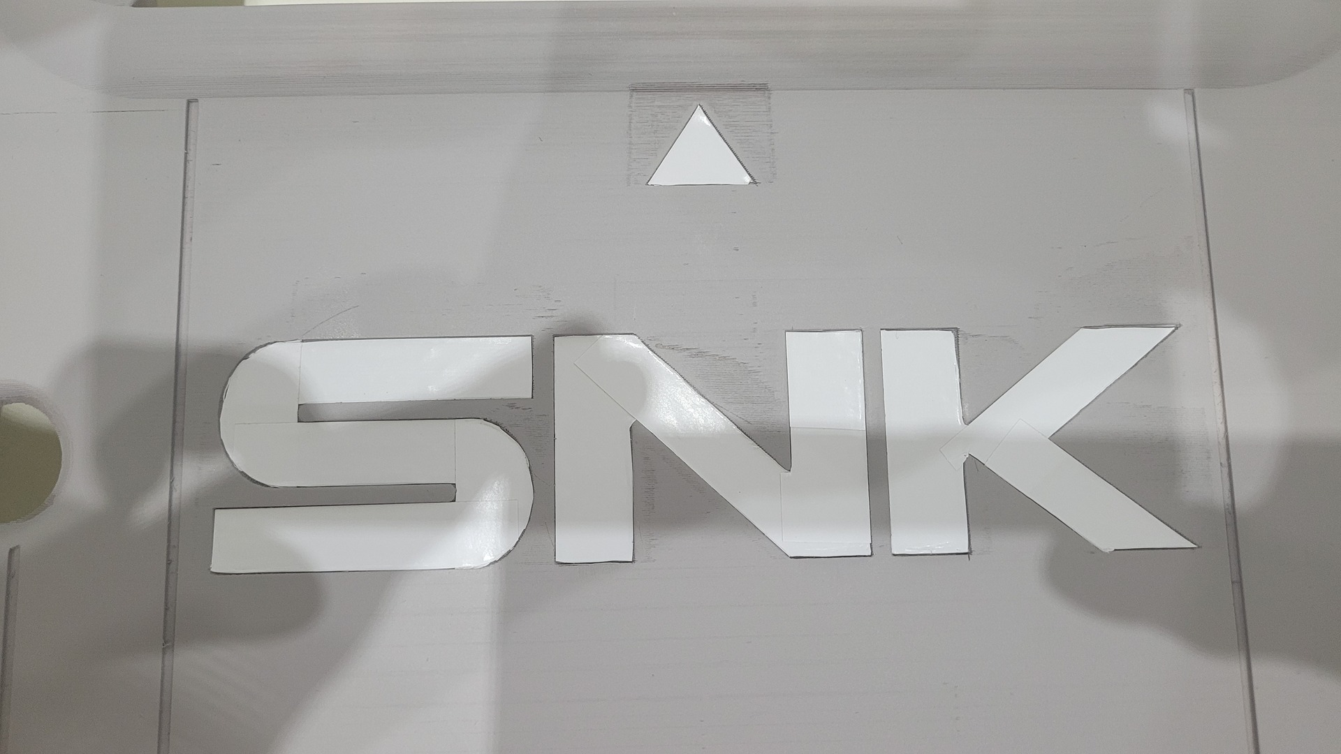
Protecting the part that will be painted in white using some adhesive tape (I should have paint them before the black) :
Both parts painted with 3 layers of black mat paint and 2 layers of mate transparent varnish. The result is not perfect, but I’m still happy with it :

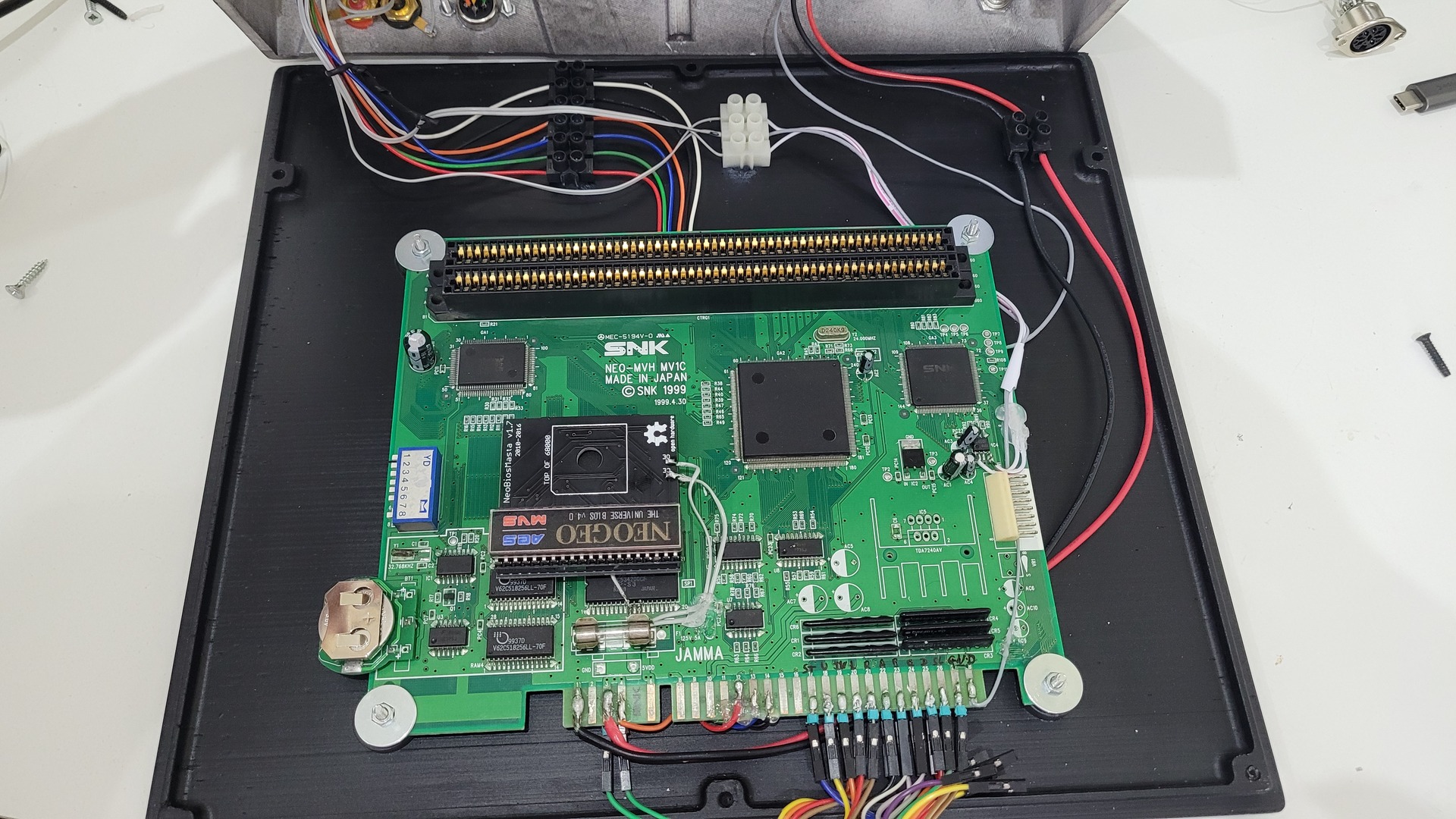
Assembling
Assembling consisted in fixing the motherboard, wiring ouputs to connectors, mounting switches and Neobiosmasta with Universe Bios.
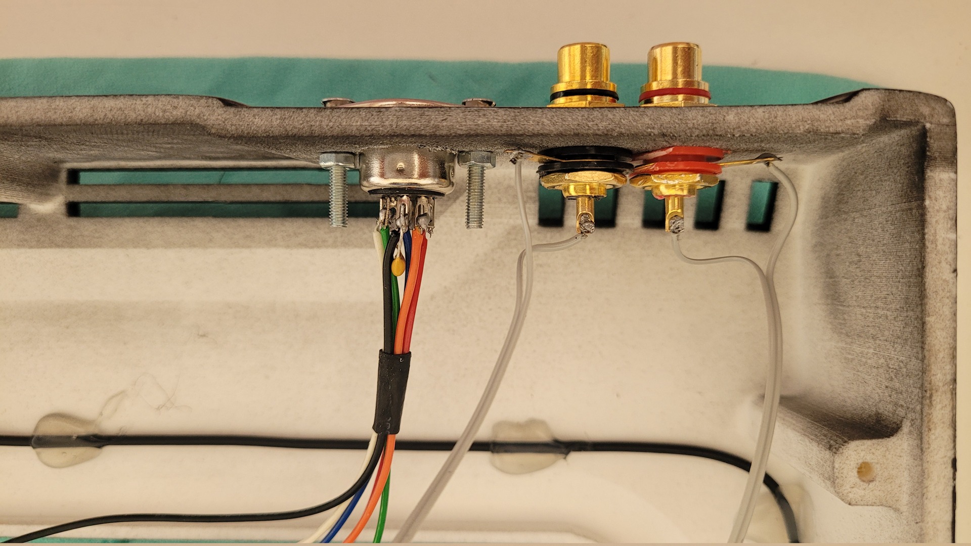
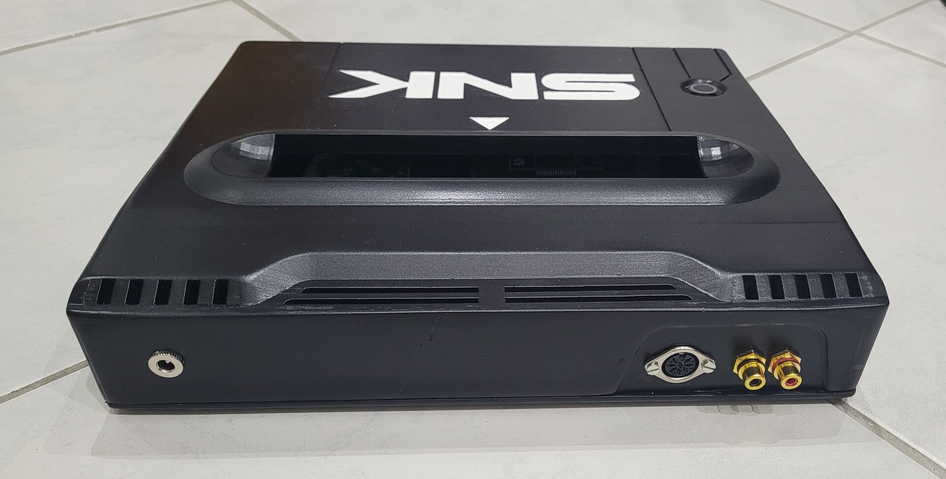
From left to right : video and audio, power connector, on/off switch and reset button:
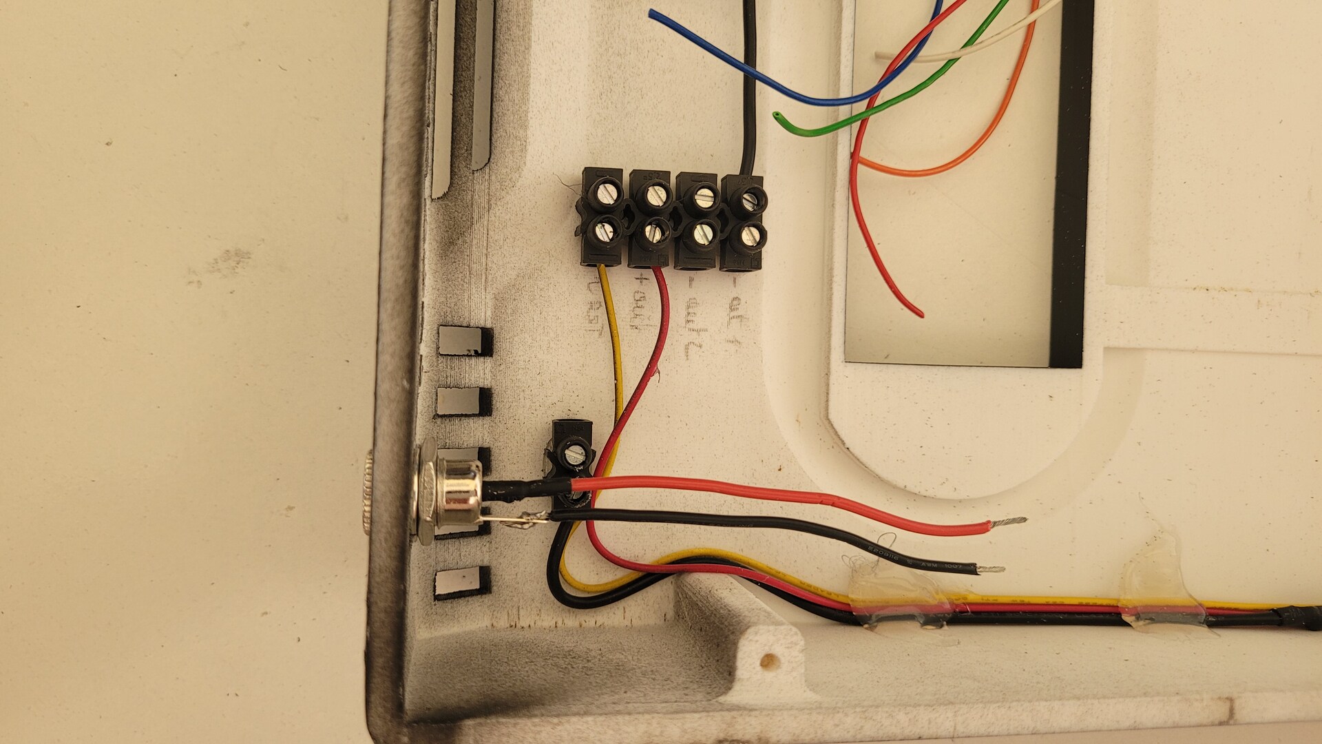
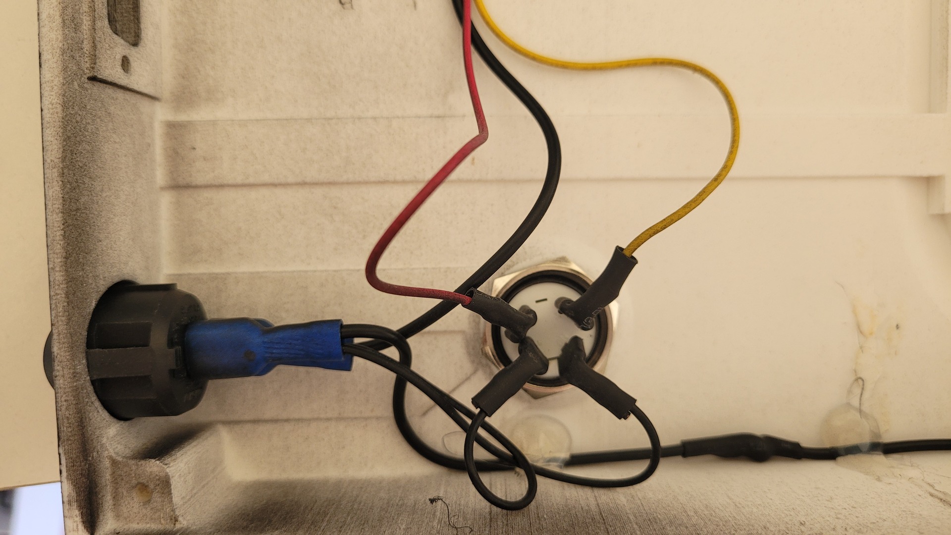
Here is the overview of the top part of the shell. I used some hot glued to fix wires and luster terminals. I used the 4 reset button pins as : +5v for led, reset signal, ground for led and ground so reset signal and ground are connected when the button is pushed (hense the console reset).
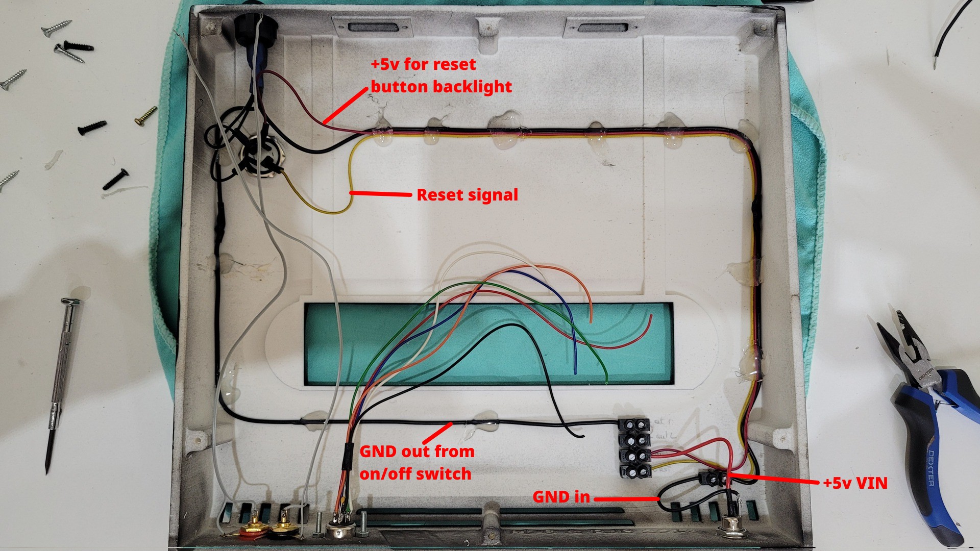
Then, fixing the motherboard, mounting Neobiosmasta and screwing all wires in the corresponding luster terminals, juste before closing the shell. Note that I used some plastic wedge of about 5mm to make the motherboard not touching the shell’s surface.
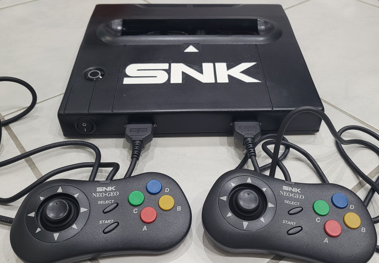
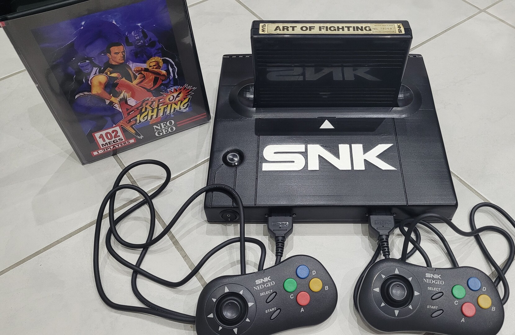
Final Result
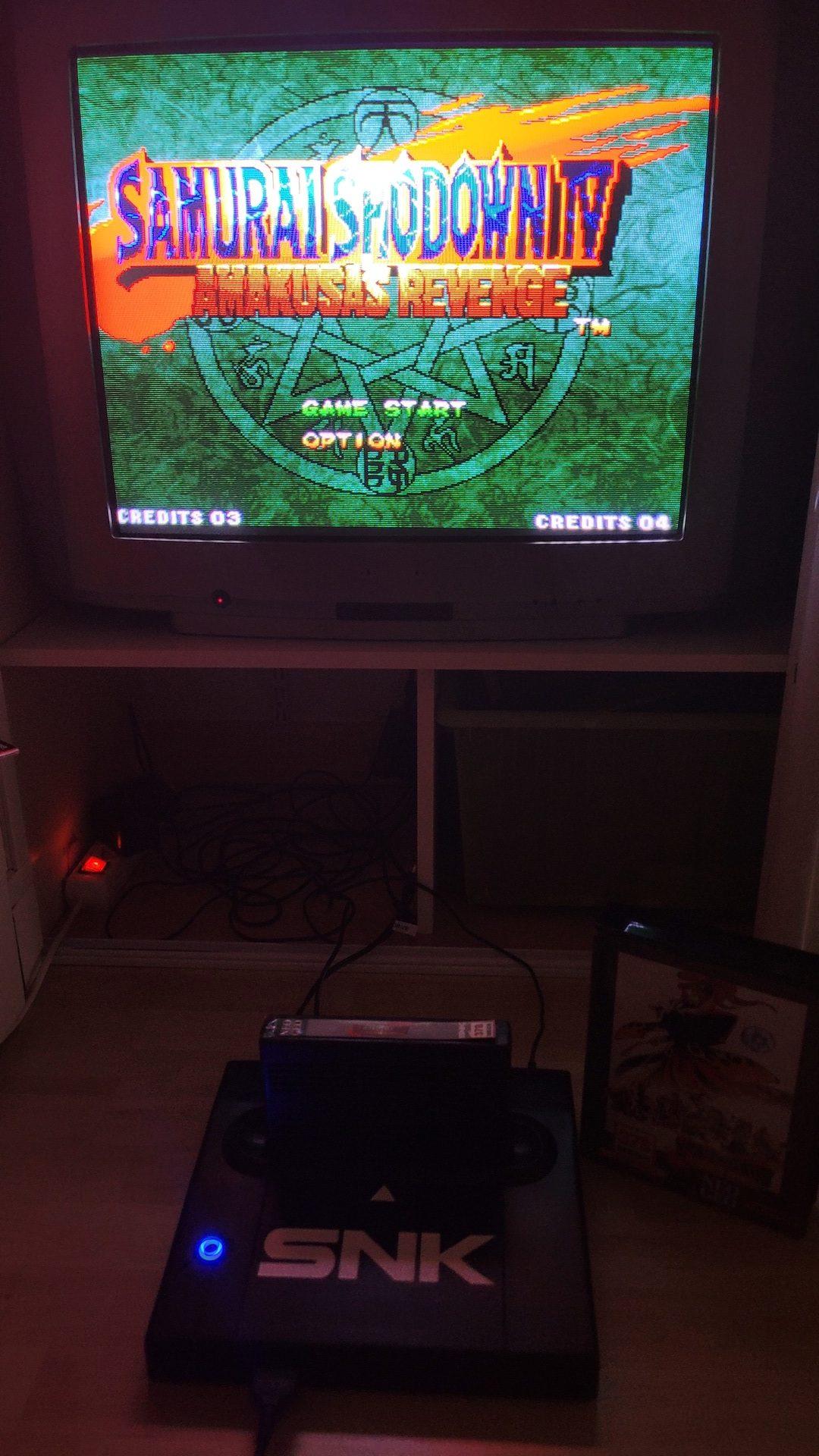
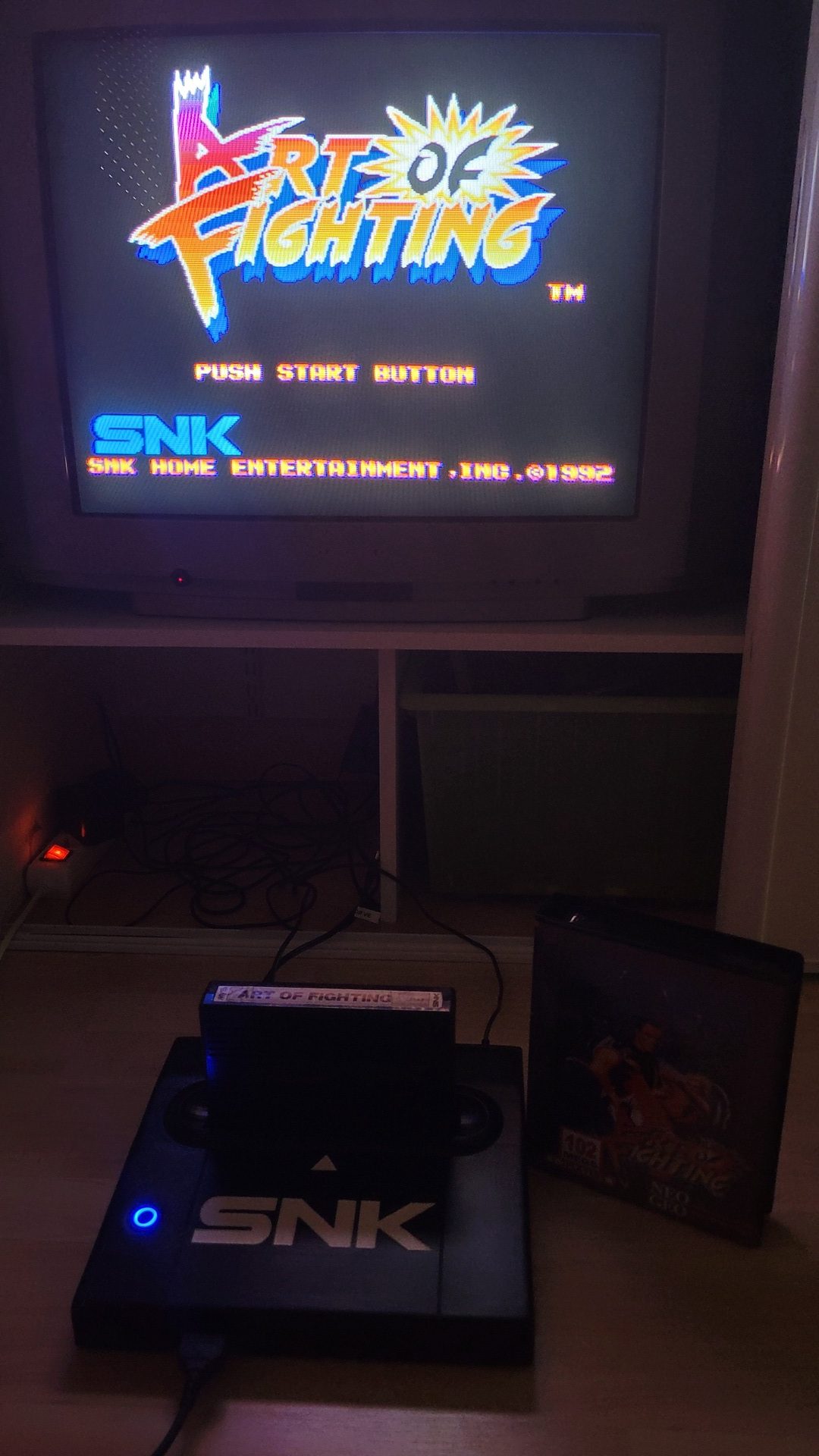
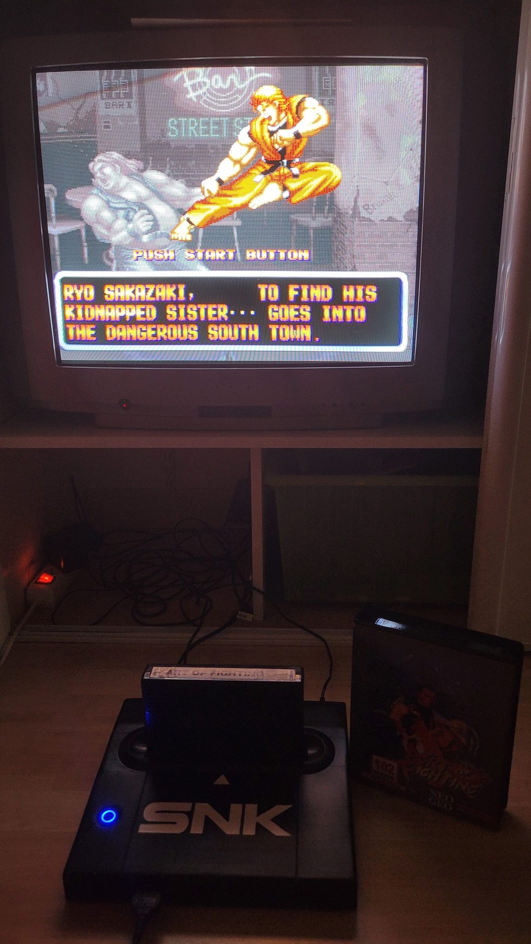
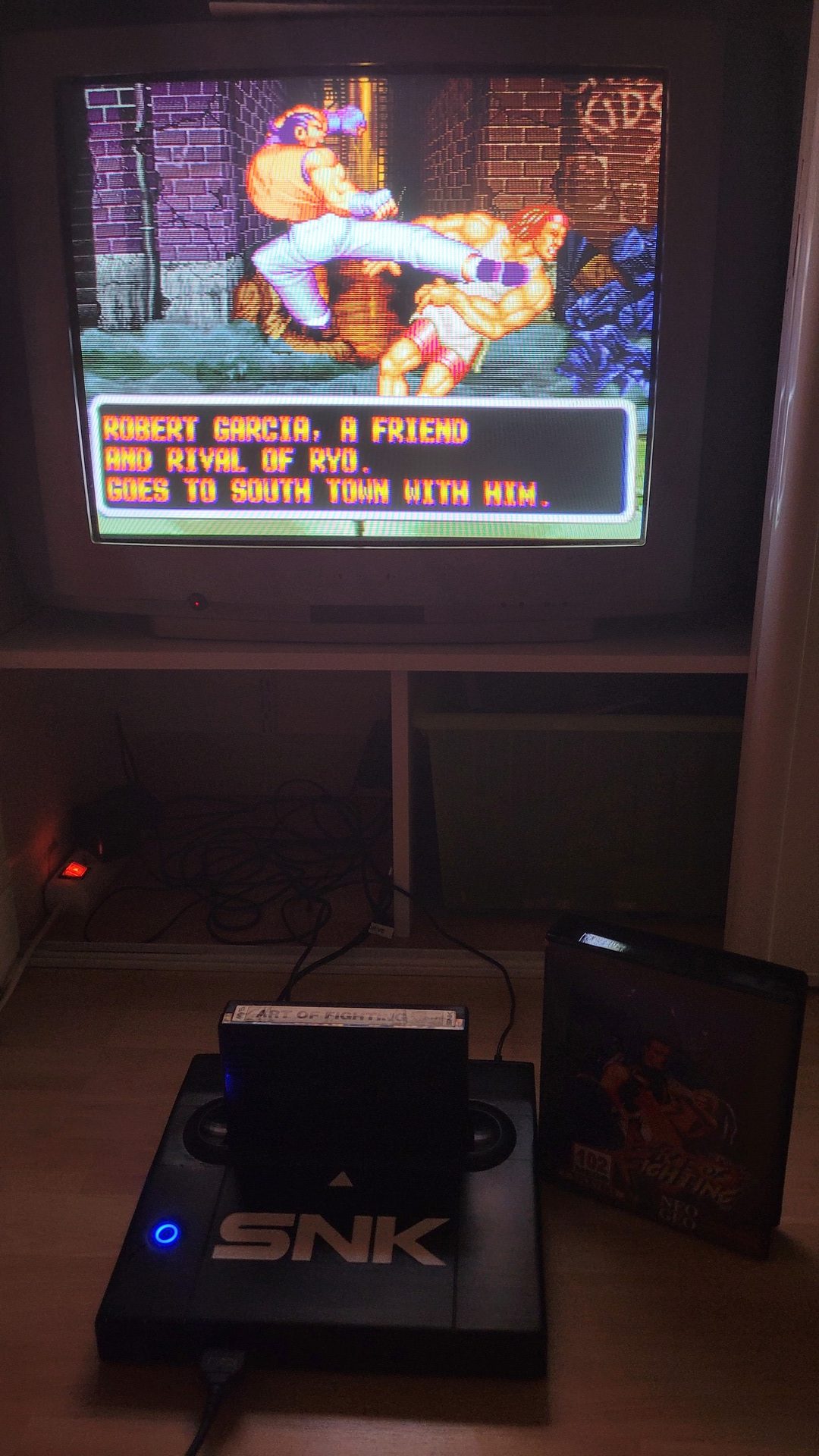
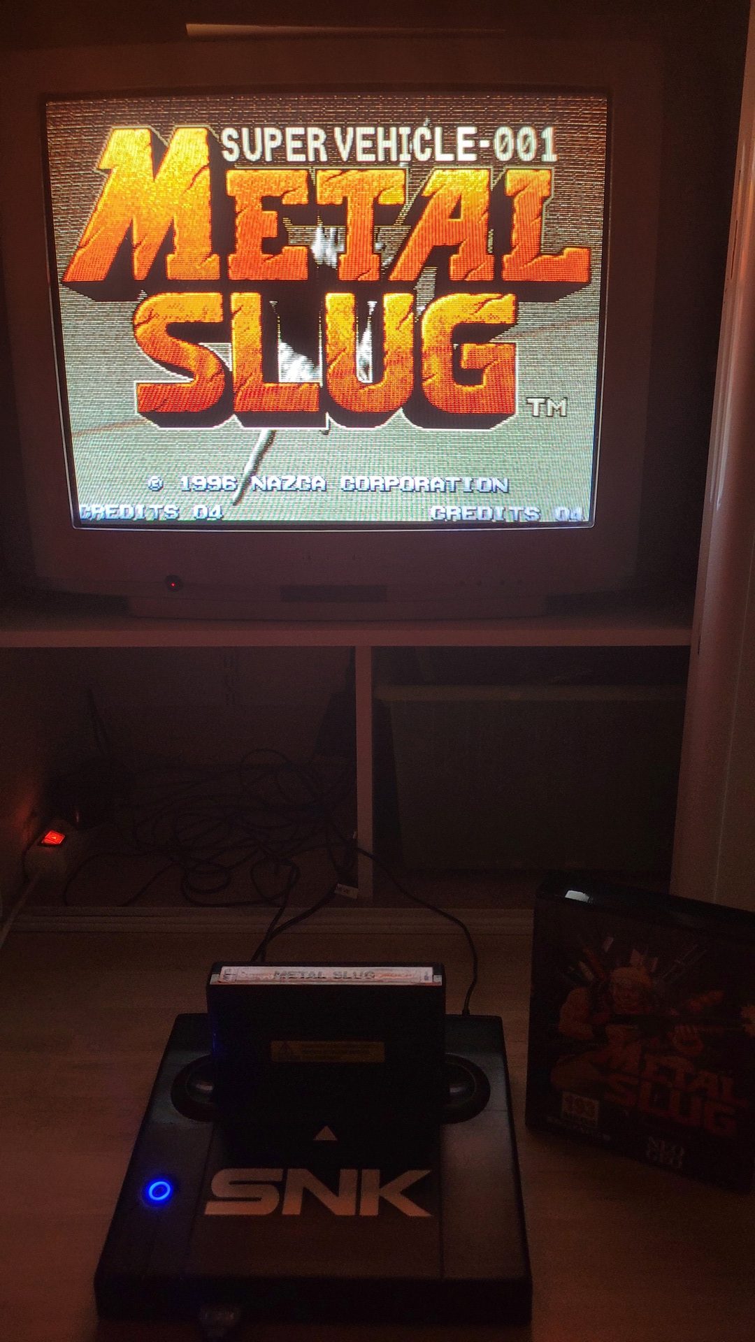
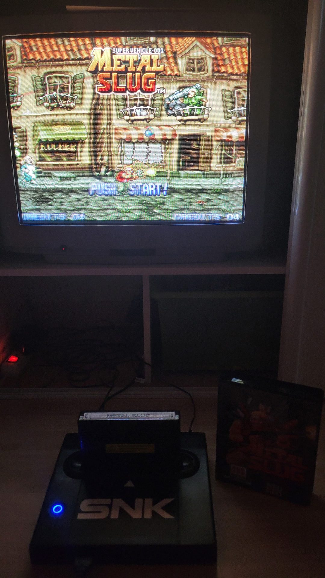
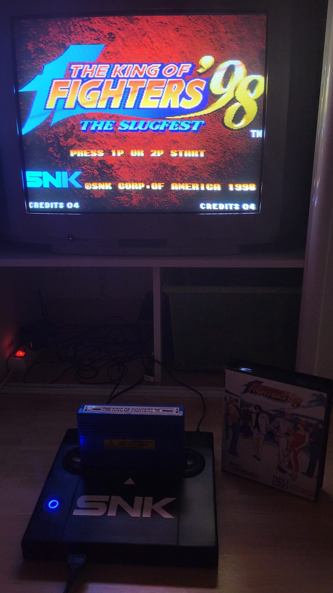
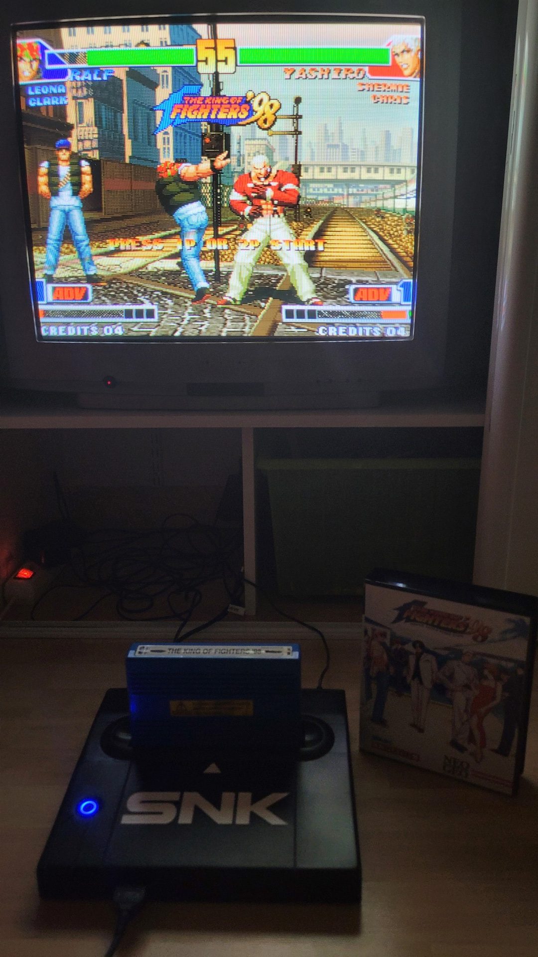
All is assembled and the two parts of the shell is screwed. Add a pair of Neo Geo CD joypads (I prefer them over joysticks), some games in beautiful shockboxes, and if it will never be a true AES console, the simulation is enought for my pleasure 🙂
And it works on a real CRT TV !