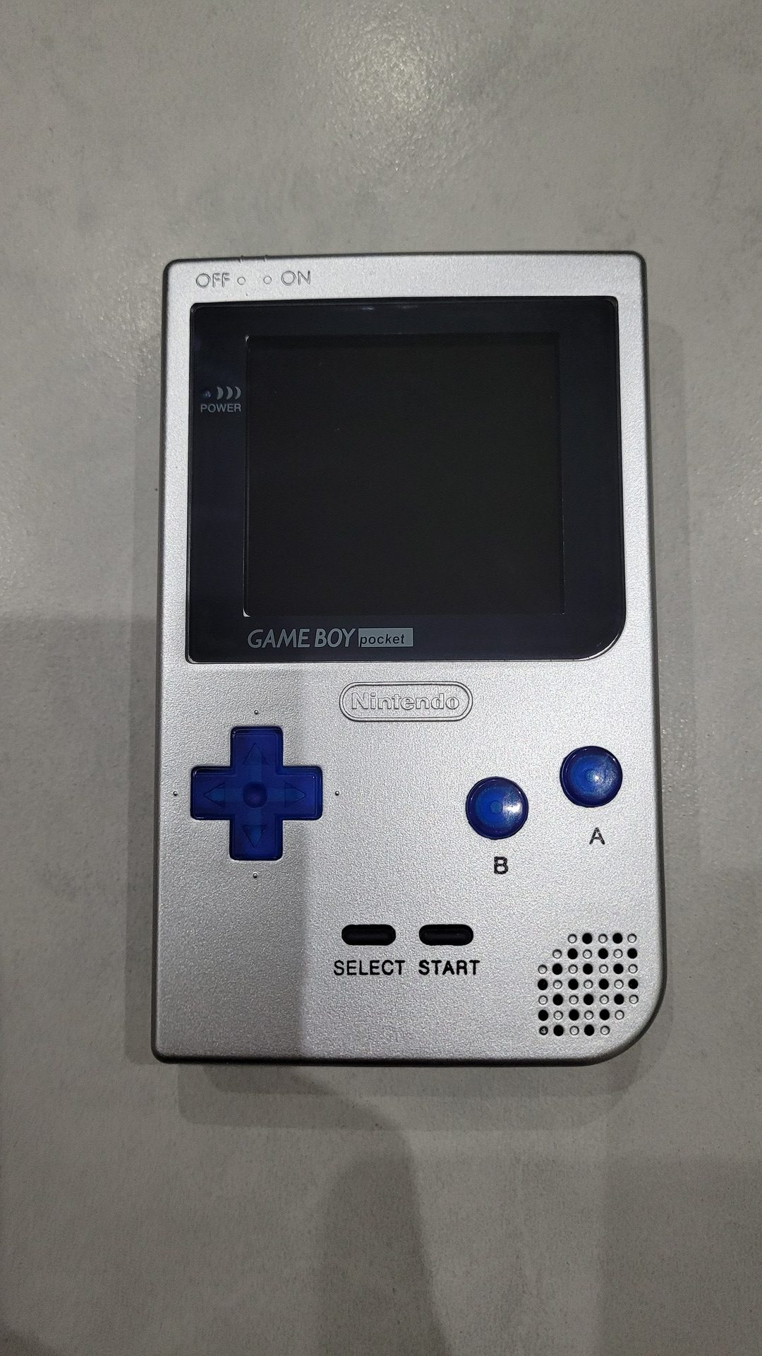
The Game Boy Pocket is my favourite model. I already modded one with backlight and bivert. This considerably enhance the display and the gaming experience. However it is still a passive dot matrix screen which makes fast action game difficult to play (eg. Donkey kong land, Super Mario land). Fortunately there is a nice solution : IPS display ! So I deciced to use such a screen on another game Boy Pocket and as the model I took was an ugly green one, I also decided to enhance it futher more : new shell, translucent backlit buttons and lipo battery.
This is the story of my second pimped Game Boy Pocket…
Needed materials
- Obvisously a Game Boy Pocket or simlpy a motherboard

- Tri-wing skrew driver
- A desoldering pump
- A soldering iron
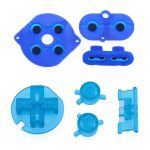
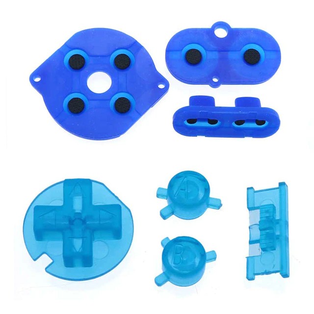
- GBP Translucent button kit
- White conductive rubbers set (white color is important to better reflect the light emmited by the leds)
- A TP4056 based lipo charger or equivalent, with input pads
- IPS LCD Kit with pre-cut shell. An IPS kit can be purchased alone, but the original shell must then be modded. As I wanted to change my ugly green shell, I took a model with the included shell
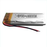
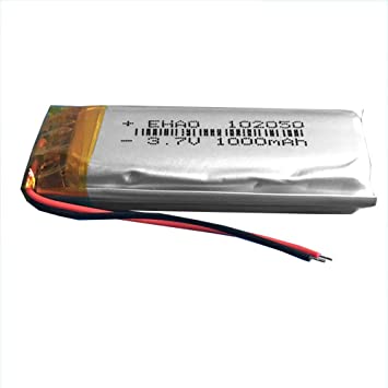
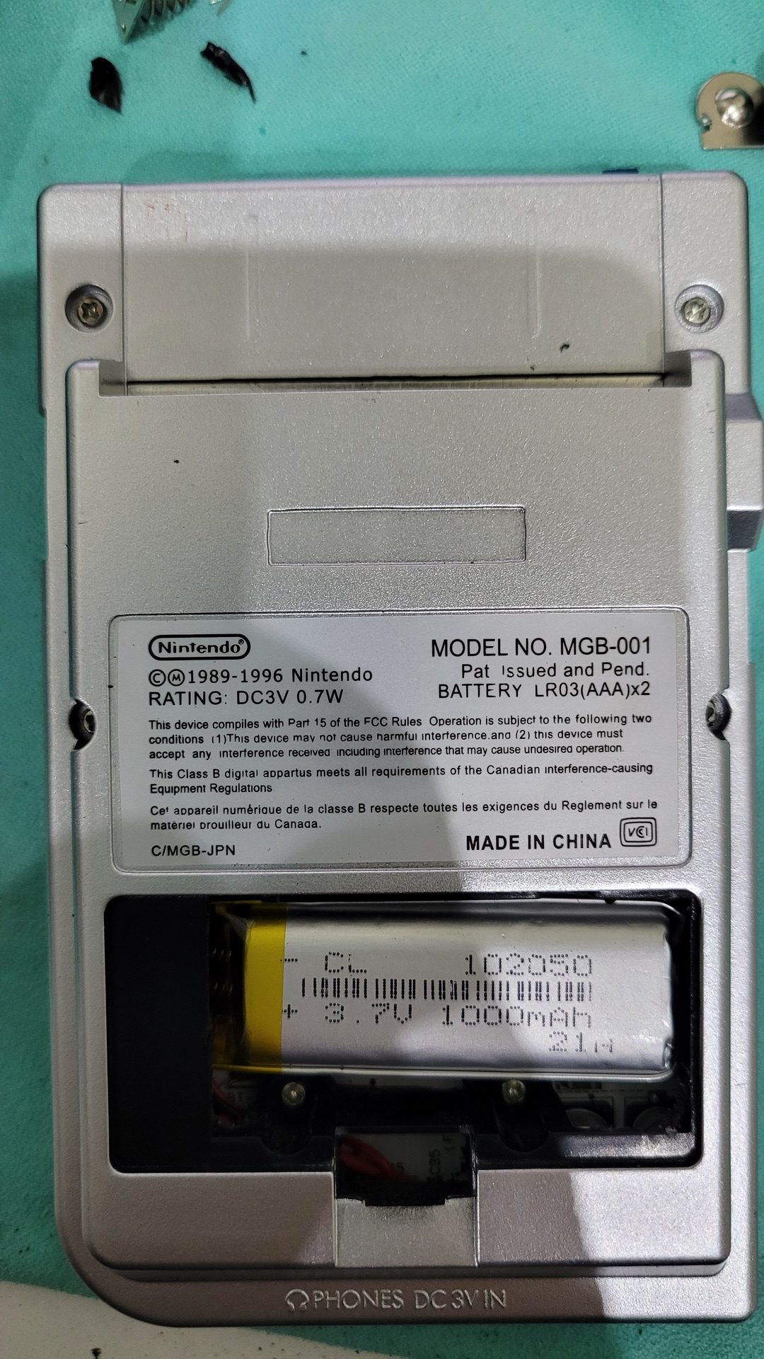
- A 102050 lithium-Ion battery
- Thin wires (I used an old ribbon cable)
- 4 x white 3.3mm leds
- 4 x 470 ohm resistors
- One blue 3.3mm led
- A pair of cutting pliers
- A dremel
- 470 uf capacitor (10v or 16v are fine)
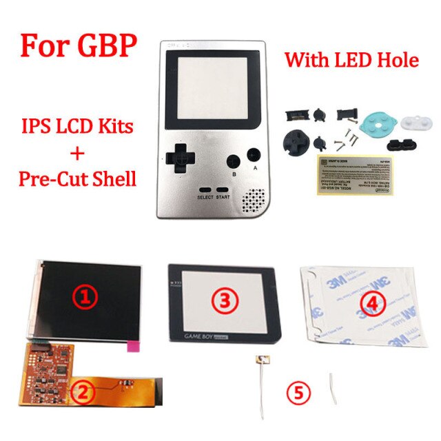
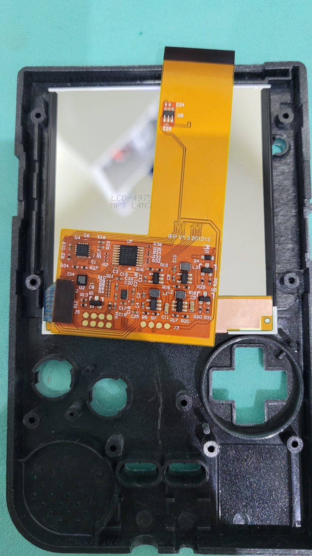
IPS Display
The kit that comes with a shell replacement is easy to install and comes with a simple howto. Basicaly, you just need to unmount the original motherboard and display, then mount the IPS display and the motherboard into the new shell
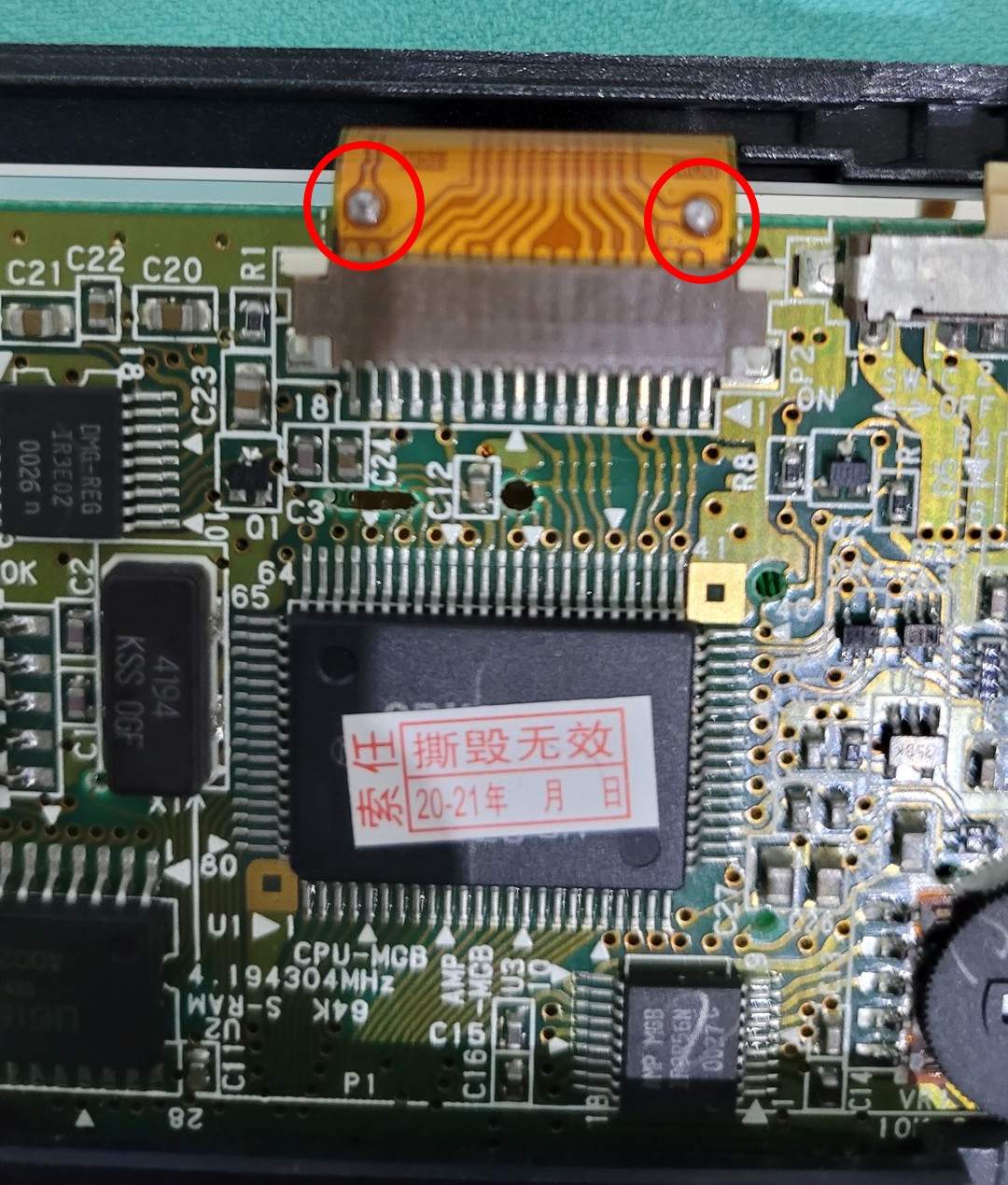
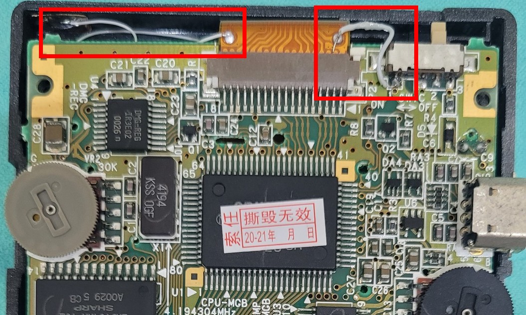
There are also 2 solder points on which some solder must be added before adding 2 wires:
- As the Display has its own power regulator, it takes its power source directly from power switch
- The other one is for a touch sensor used to change the color schema of the display
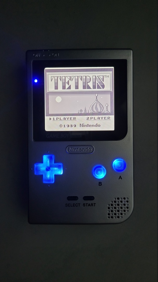
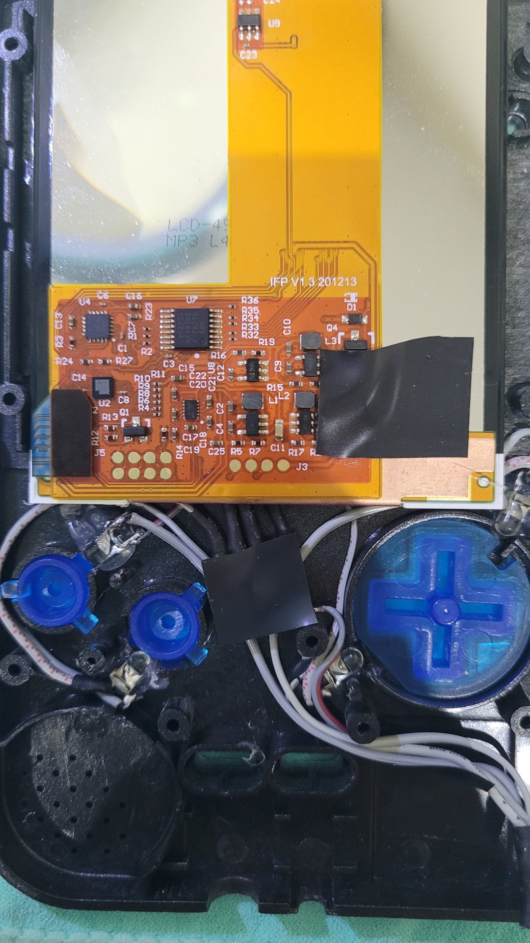
Backlit buttons
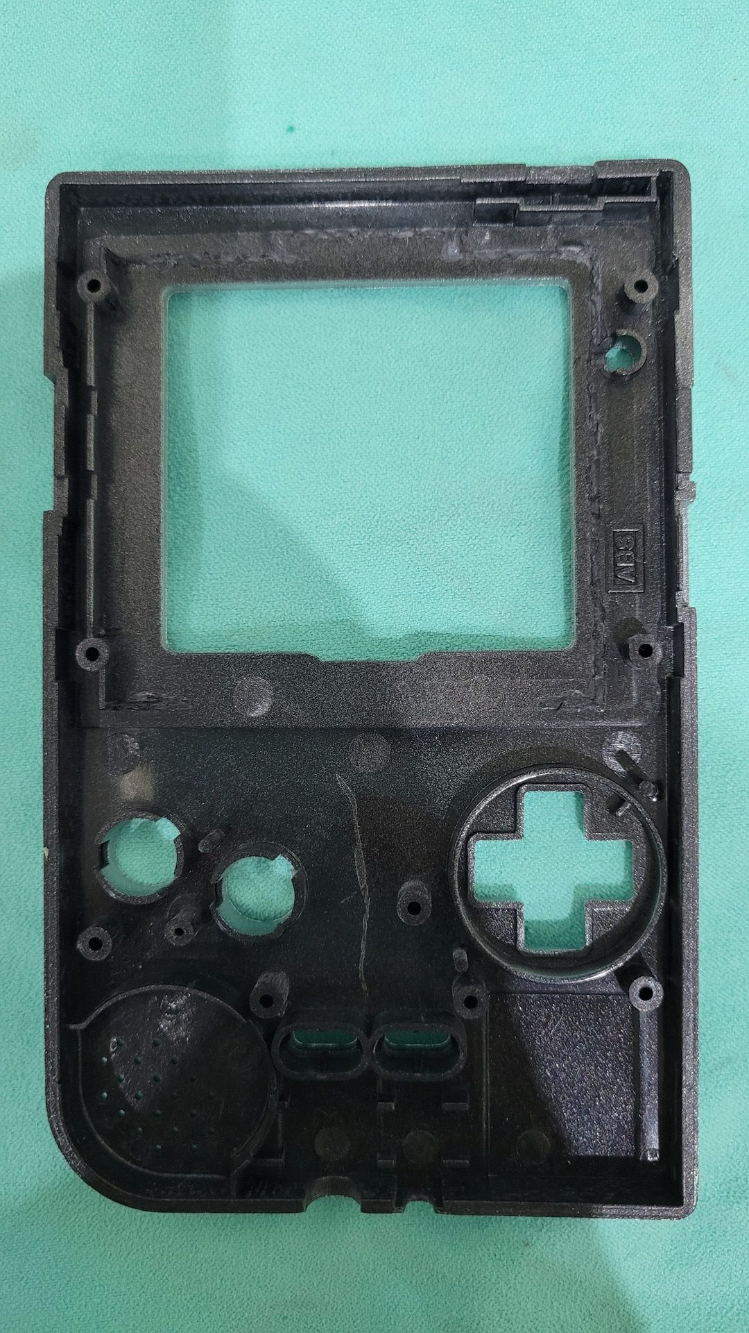
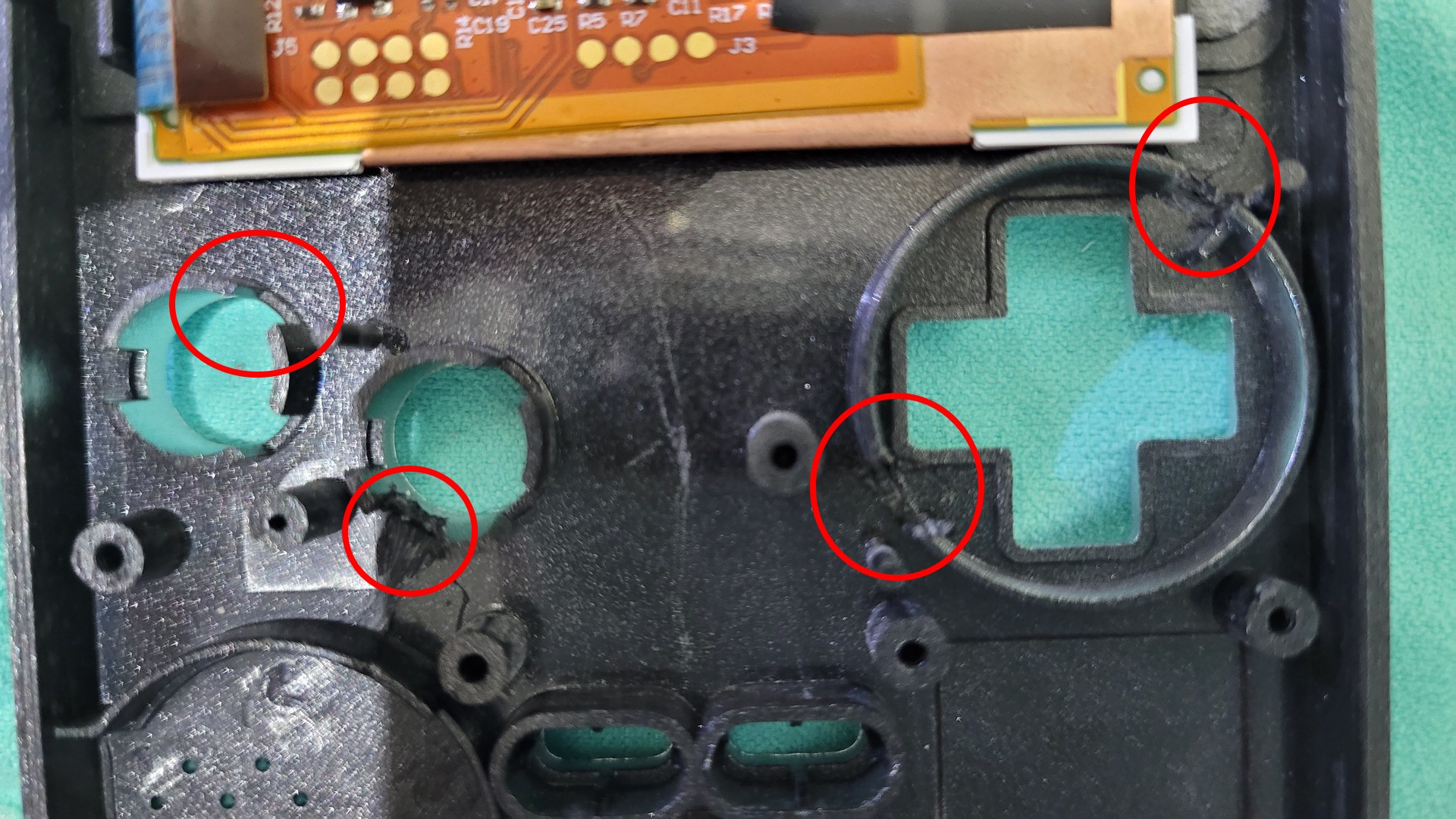
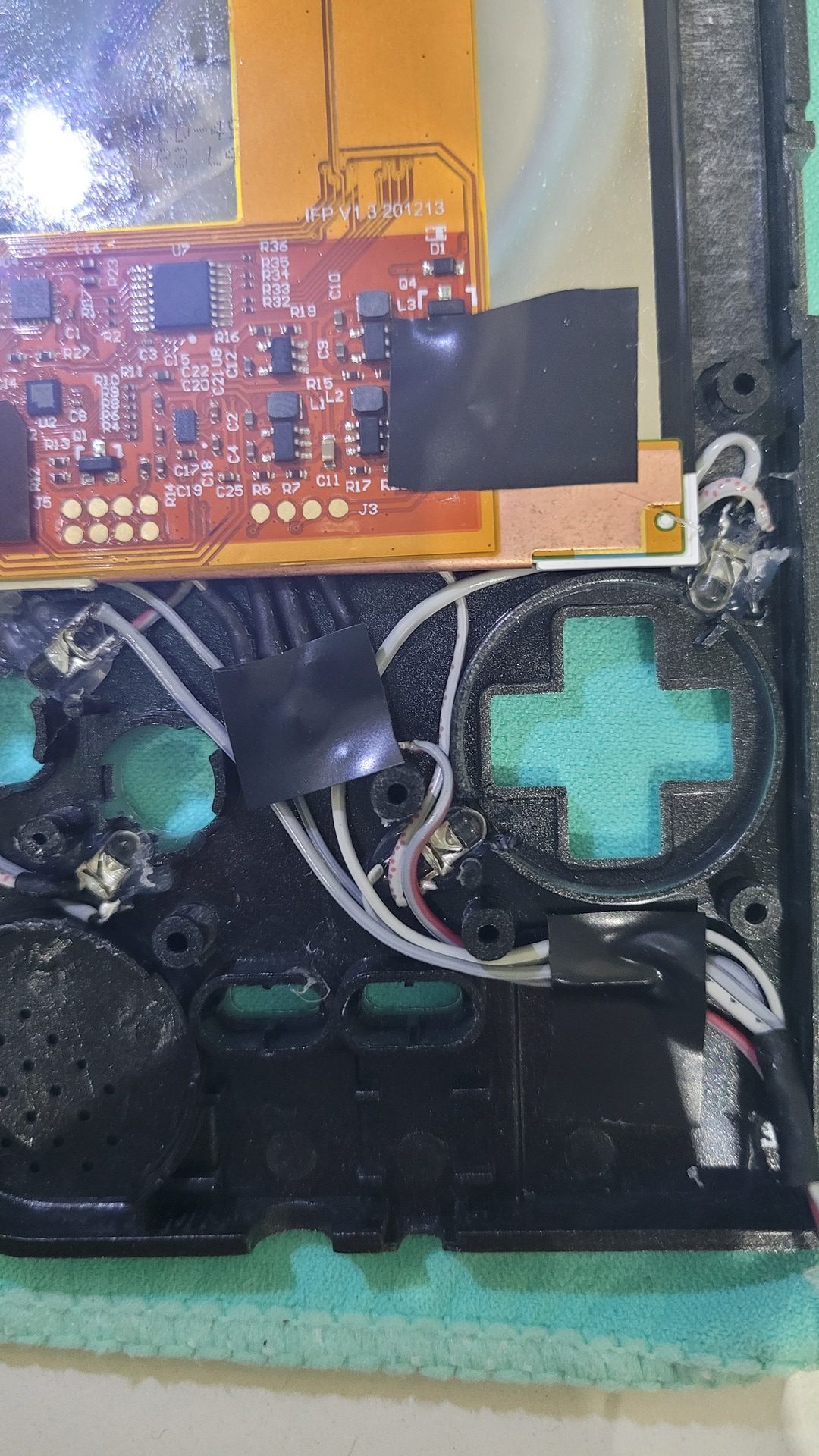
I used 4 leds : 1 per button and 2 for the dpad. To fix the leds so they can enlight the translucent buttons, I cut some parts inside the shell
Next, I prepared all the four leds by cutting the legs very short and add wires I got from an old ribbon cable (the cables needs to be very thin). Then I fixed the leds with hot glue.
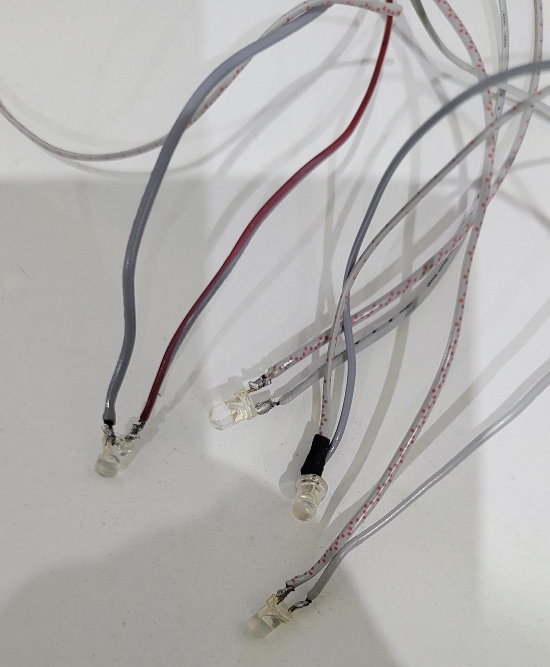
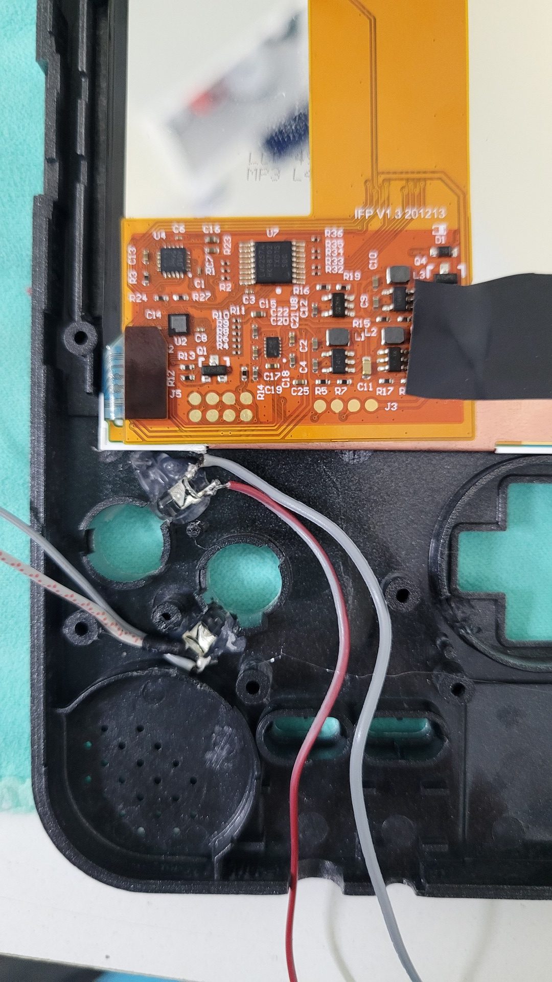
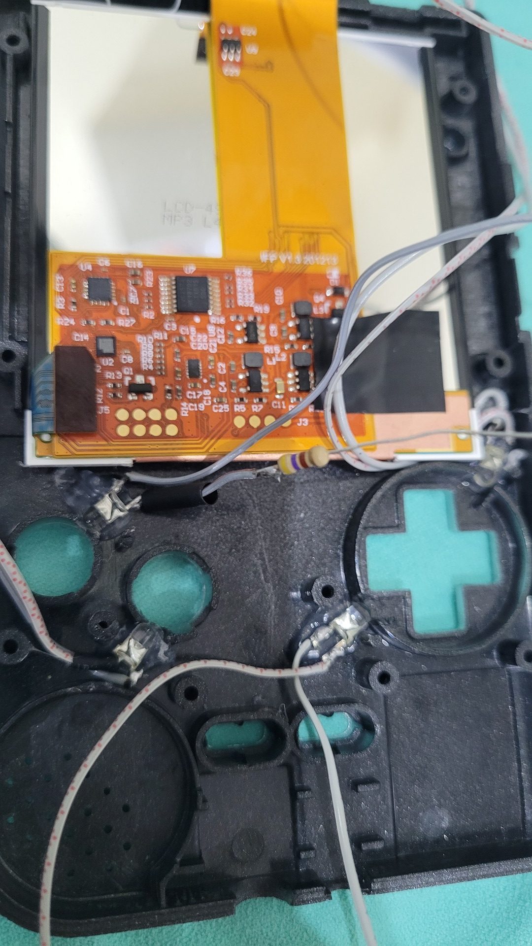
With the leds fixed, it is easier to align all wires in order to solder the resistors so they are all aligned on the center of the console. Note that I used some heat shrink tubes to protect resistors output to the positive legs of each led.
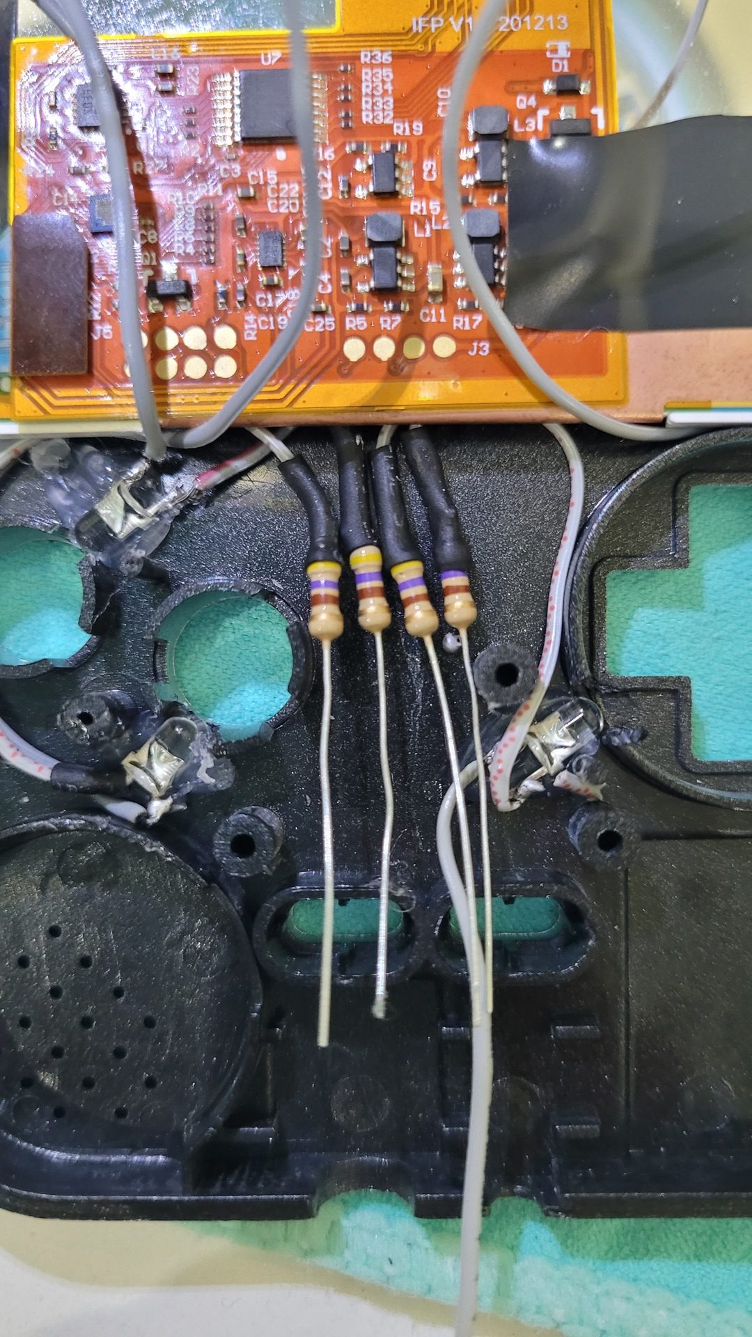
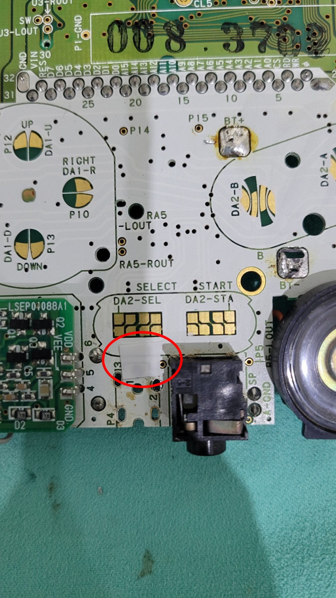
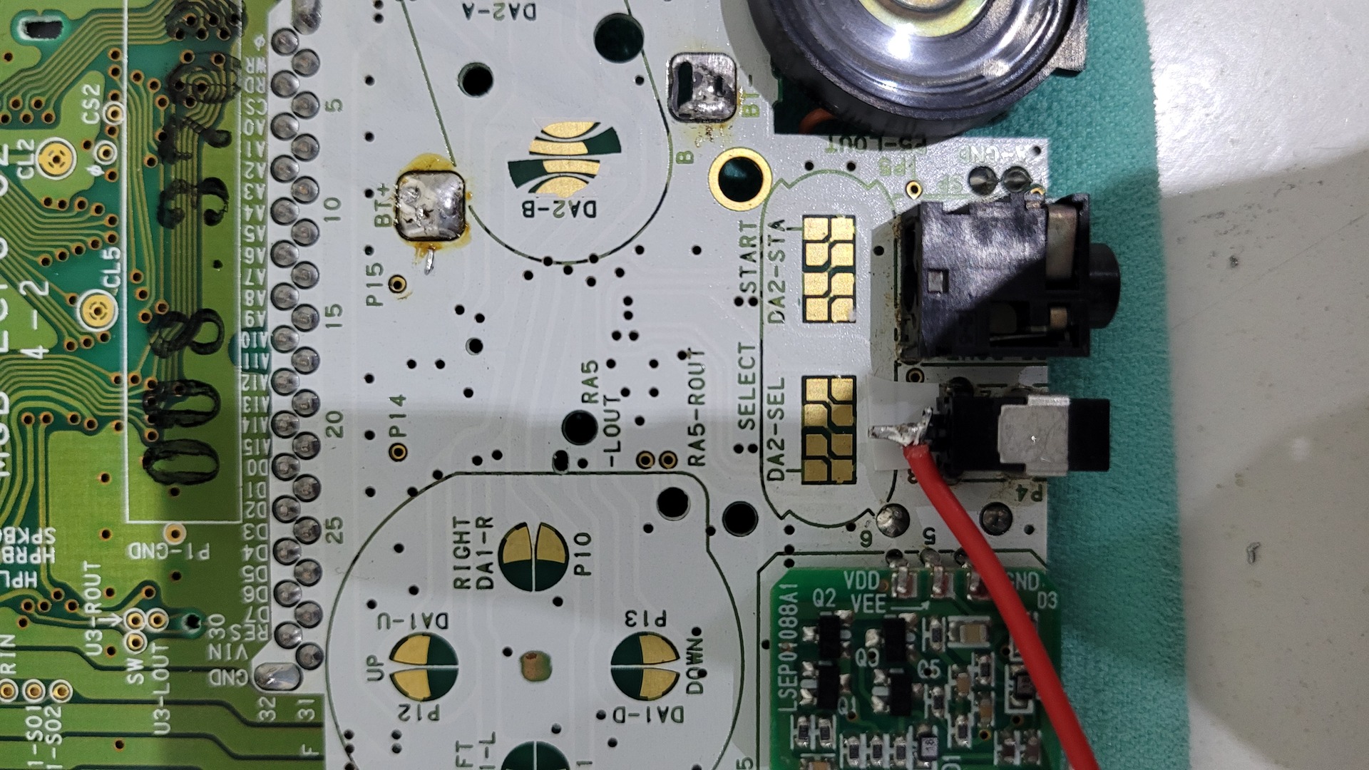
As the current input is however the same for all leds, I used a resistor leg that has been cut to link all resistors inputs together. From there, a single wire will go to the battery. Regarding the ground, all wires are soldered together on the bottom right part of the shell. Thus there is one wire for the ground and one wire for the positive, and they are placed just under the power source pads on the motherboard.

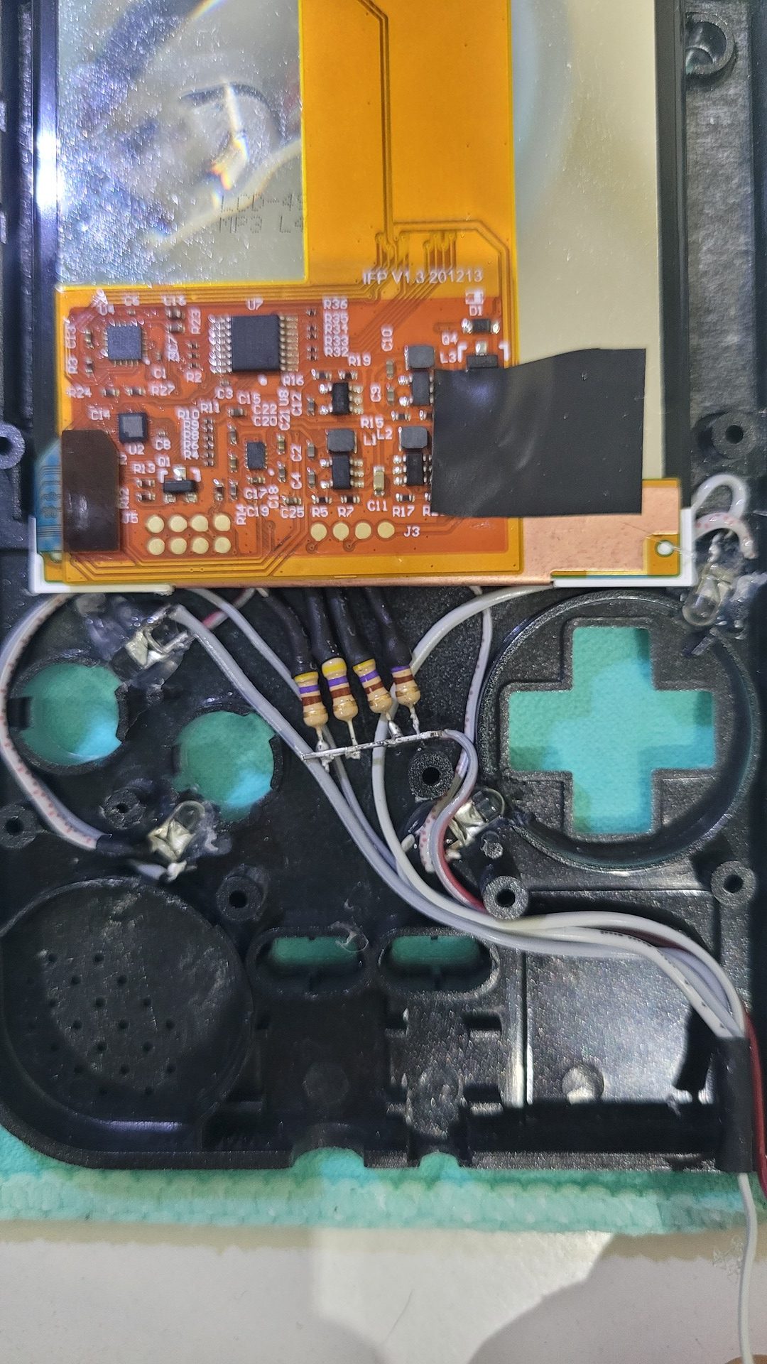
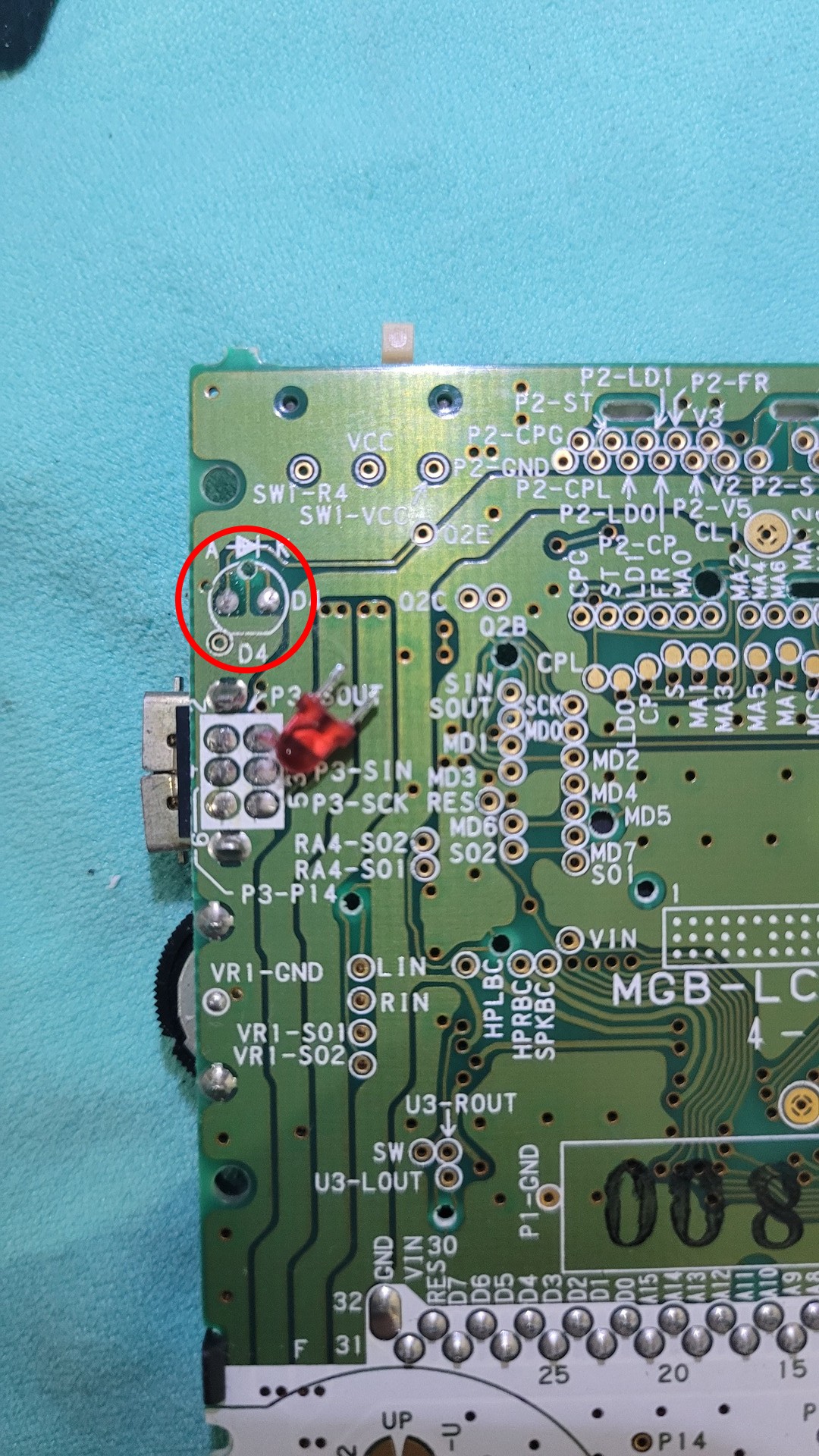
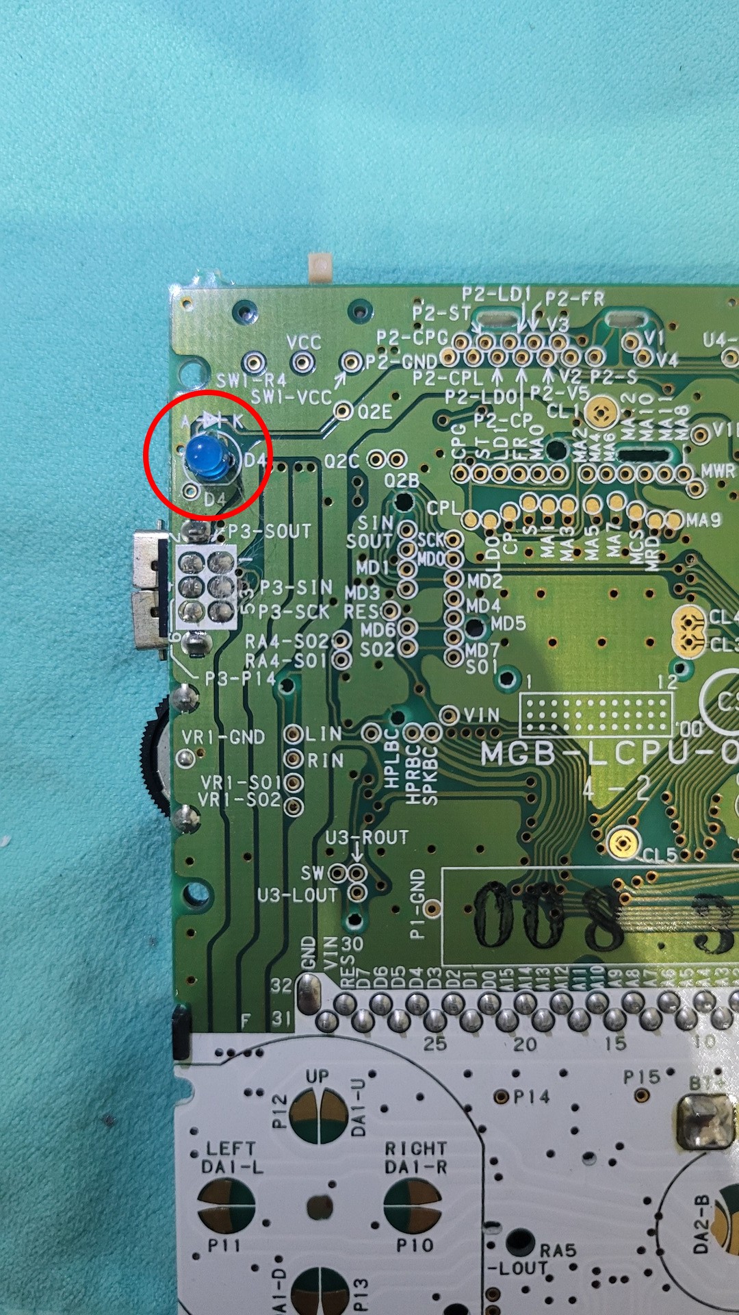
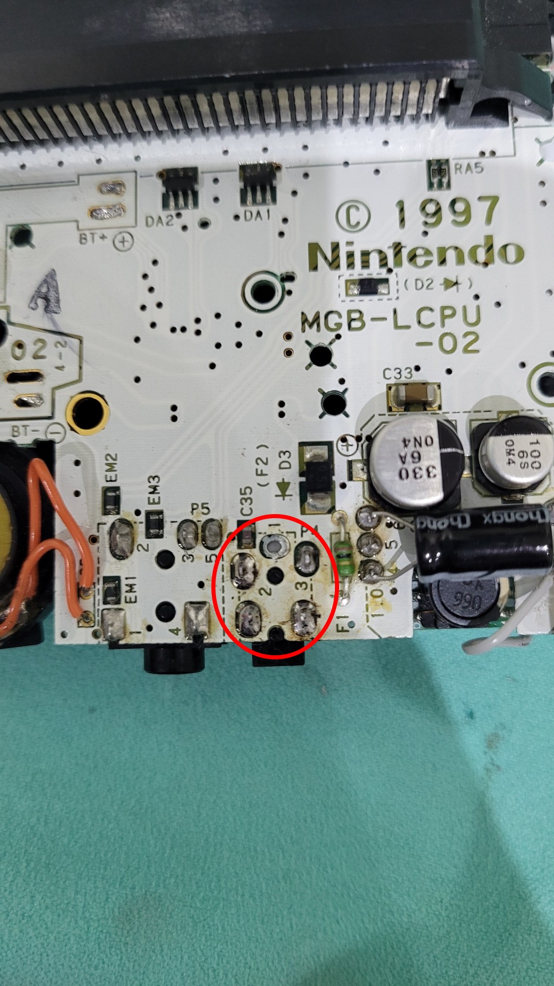
Final leds step : replacing the original red led that is used to monitor battery level. I just desoldered it with a pump and replaced it by a blue one. I know that the resistor should be bigger for a blue led, but it works well with standard AAA batteries. However it becomes a little bit too bright with lipo mod. I may change this later…
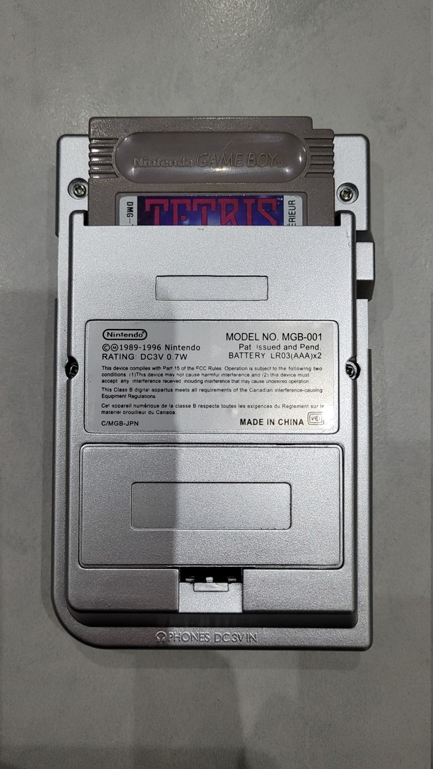
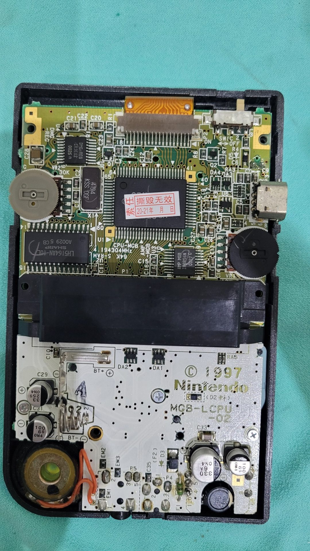
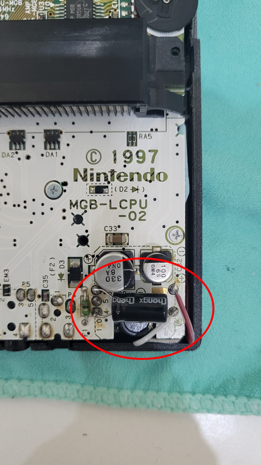
At this time, the motherboard can be remounted and the Game Boy can be used with standard AAA batteries. As you can see, I also put a decoupling capacitor (470 uf) : it helps to enhance battery life with some cartridges like pokemon or flash carts.
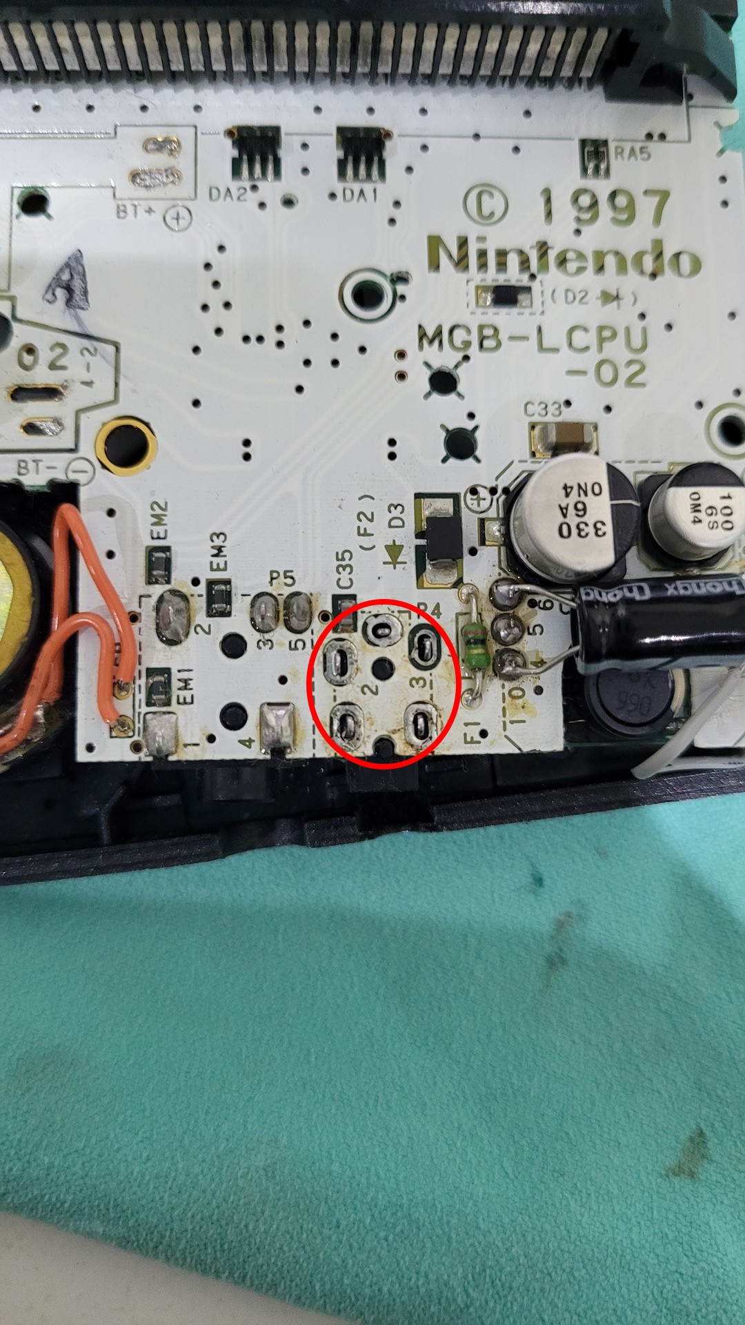
The leds wires are soldered on the pads in the bottom right part of the motherboard. Theses pads come directly from the power switch (which is directly wired to batteries)
Lipo battery
I did this mod some time after the leds and display mods. That’s why some photos show the motherboard alreay mounted and some desoldered wires.
Prepare for new power source
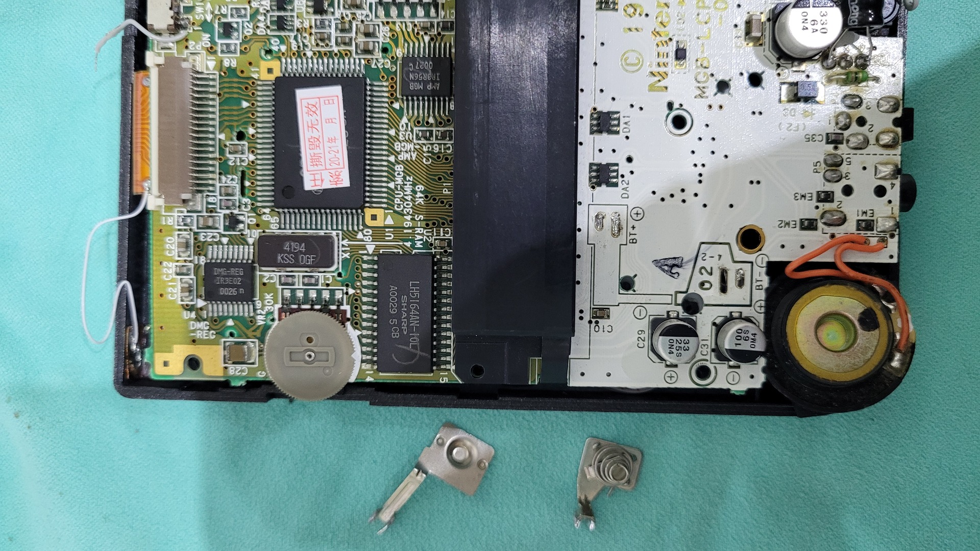
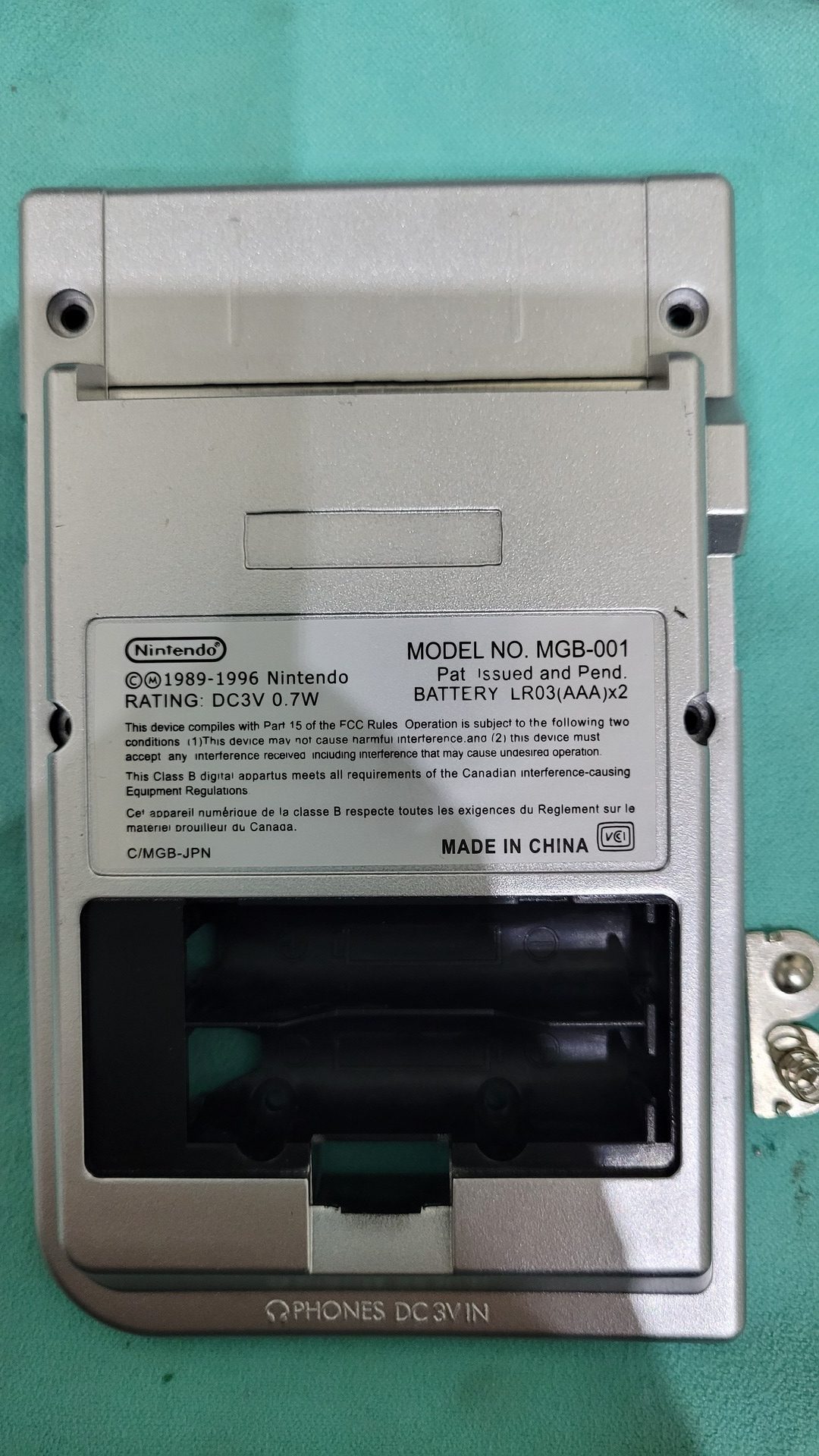
The goal is to use a lipo battery insead of standard AAA batteries. So the first step is to completely remove the orignal metal pad and spring.
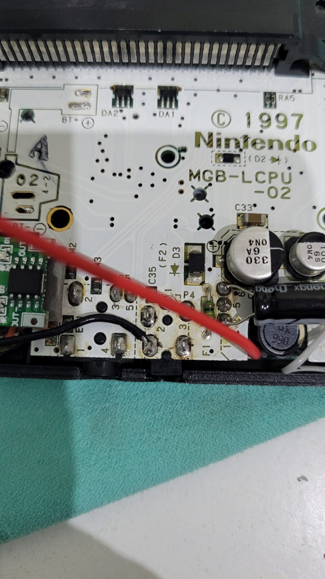
Next, I wanted to use the original 3.3v power barrel connector to charge the battery. I could have used a micro USB connector but I personnaly find it more fun to keep the orignal connector.
So, I desoldered the original barrel connector with a pump, bent the positive pin and resoldered it in place. Thus the ground is still connected to the motherboard, but the positive pin is not. This allows to use a wire that will feed the lipo charger.
Note that I also put some insulating tape over the solder point where the connector’s positive pin should be, in order to avoid any possible contact between the connector and the motherboard.
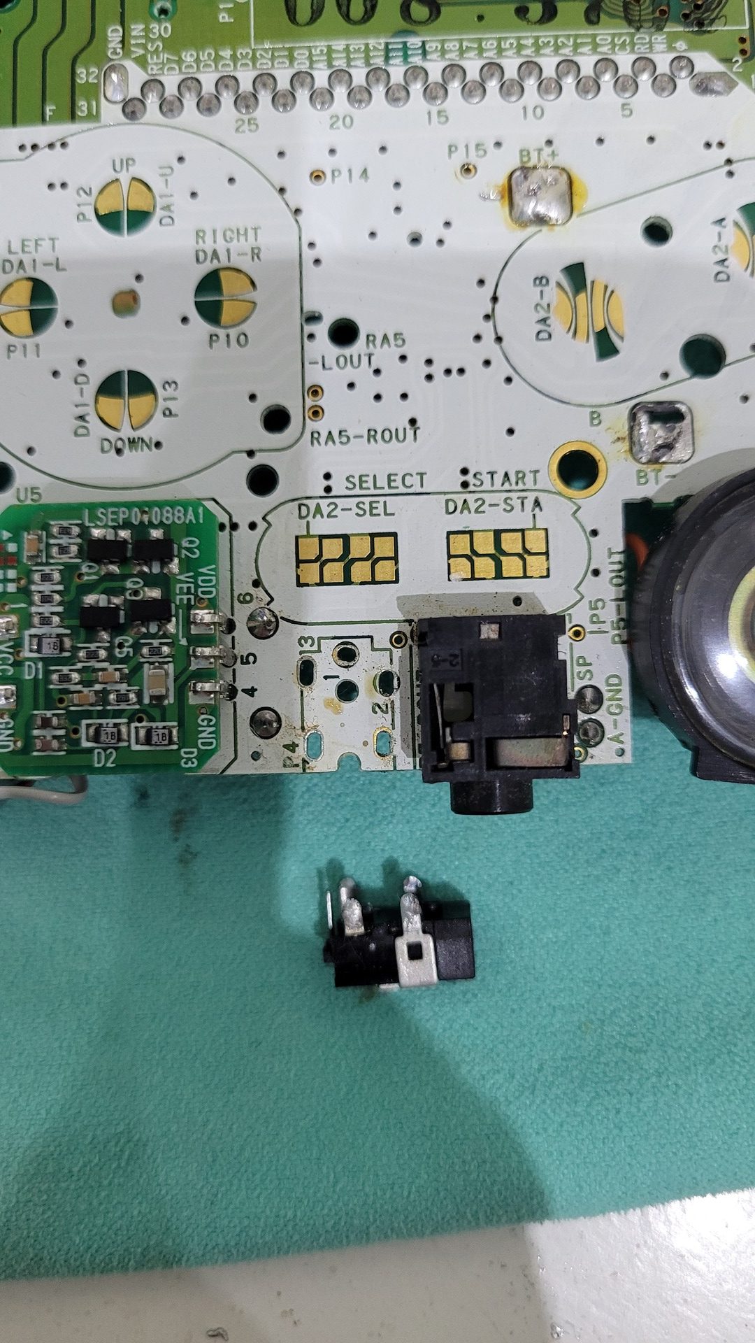
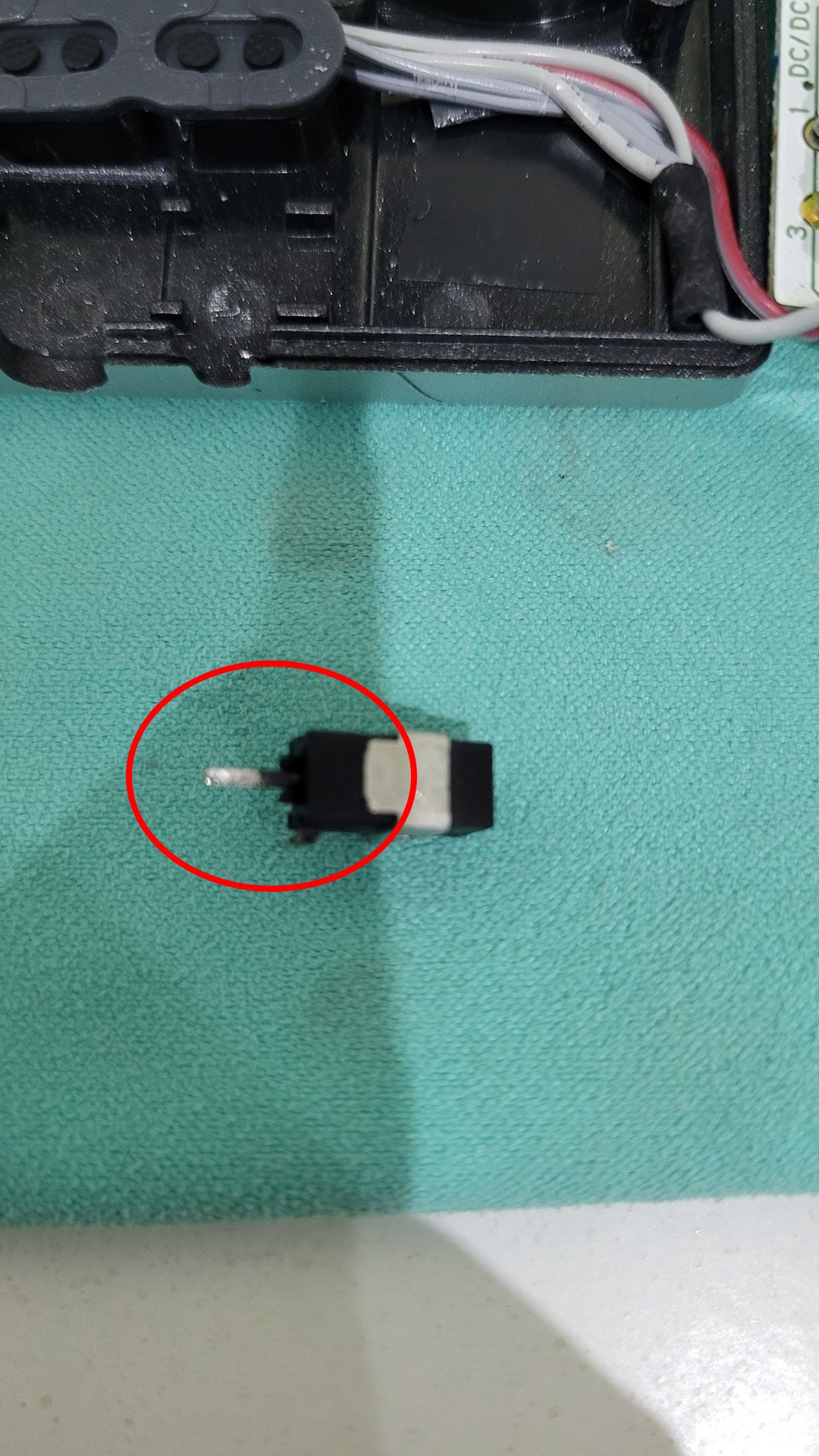
Here is the re-soldered power connector and the wire which is ready to go to the charger:
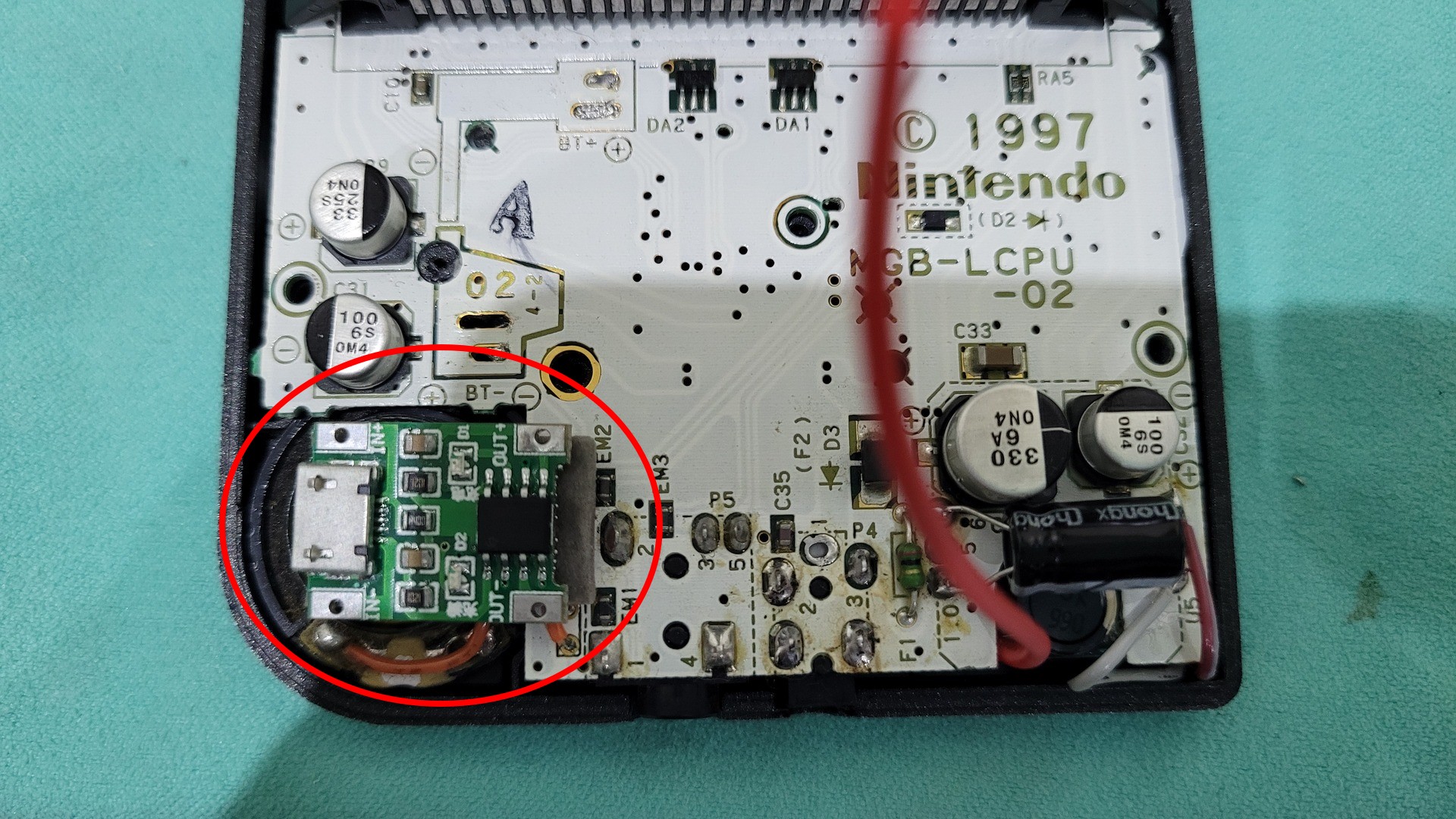
Charger and battery
The only place I found for the charger is over the speaker. I used some double faces tape to fix it, which also isolate the charger board.
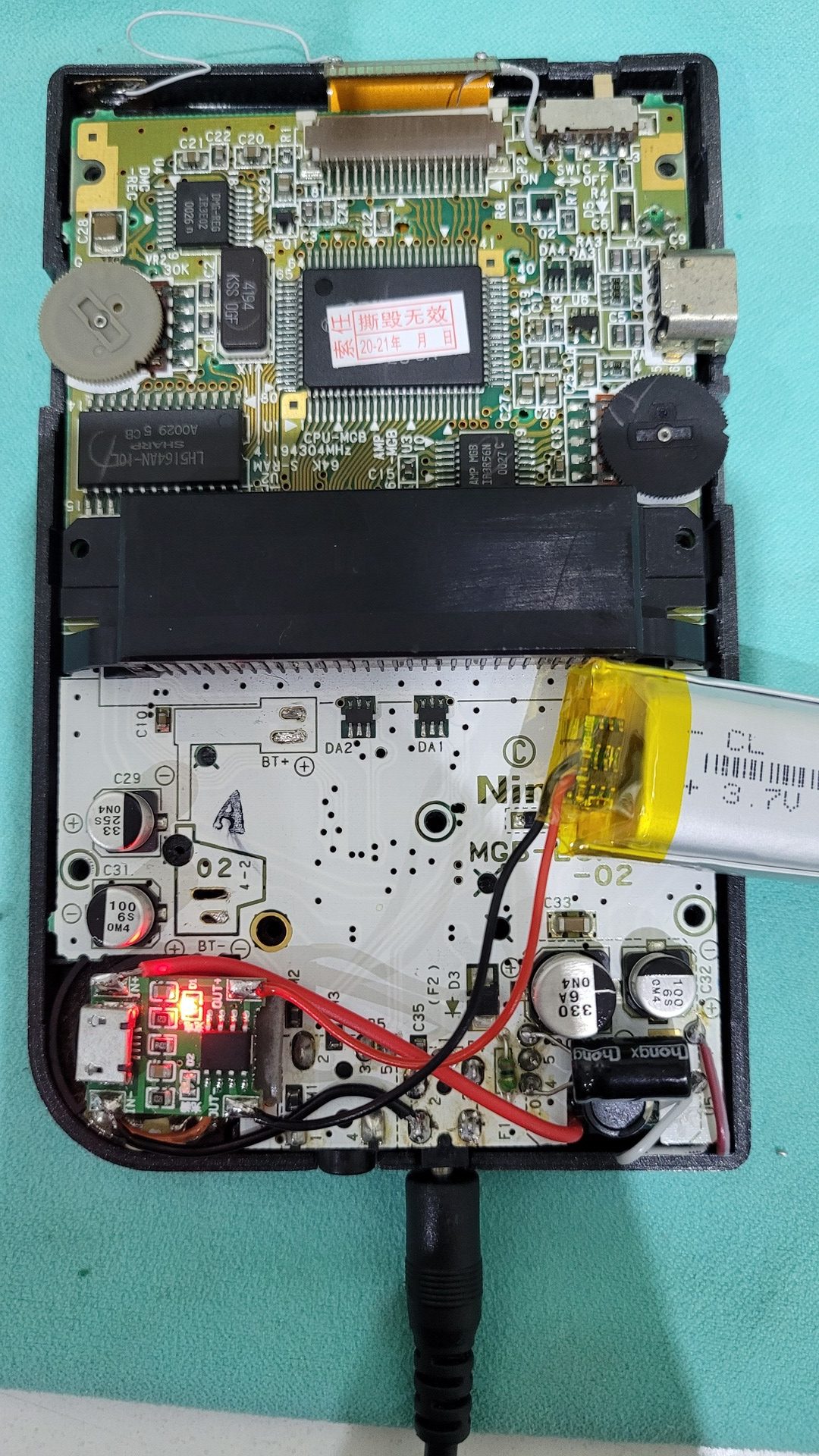
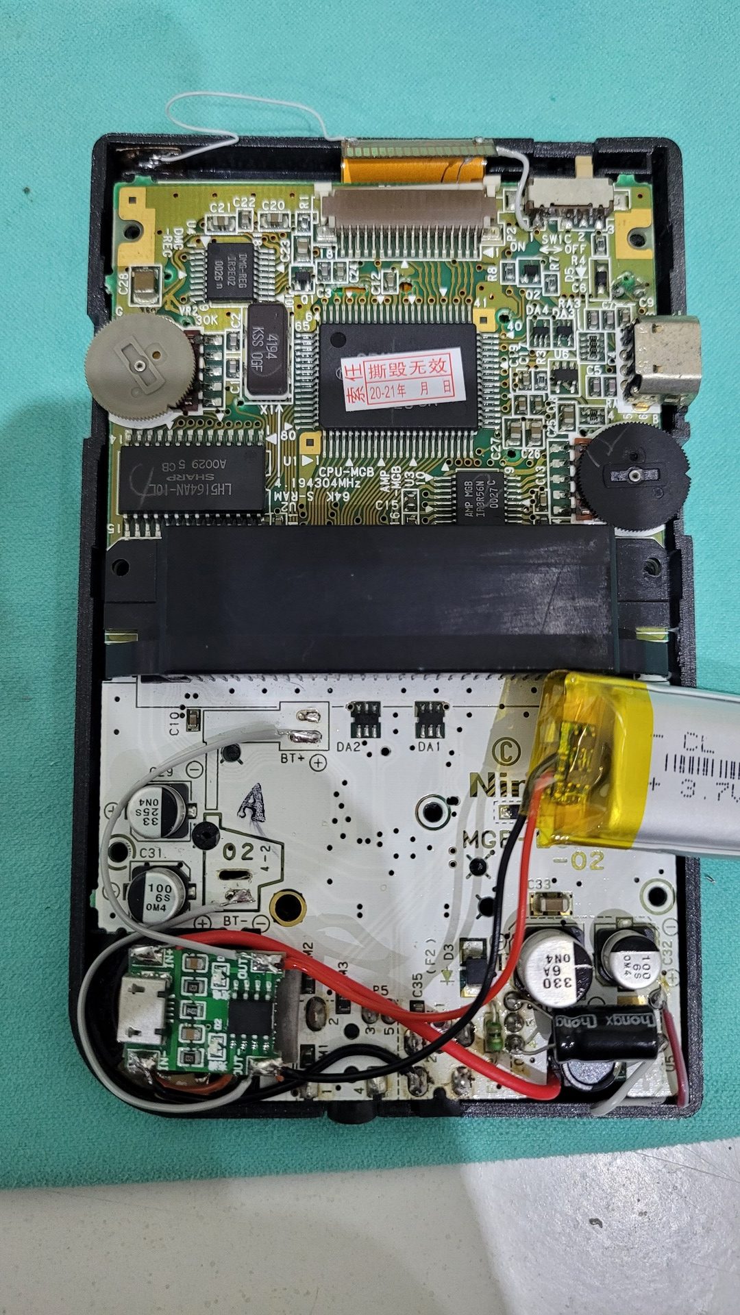
Then, the ground and positive wire that come from the power connectors are connected to the charger’s input, the battery is wired to the charger’s output as well as the original Game Boy Pocket’s batteries connectors.
One AAA battery delivers a maximum voltage of about 1.61 when it is brand new. This means that the Game Boy could accept at least a input of 3.22V. A lipo battery can deliver 4.2V when fully charged so the question is : is there a danger to wire a lipo battery directly in place of two AAA batteries ? Well, from what I have read on the internet, the Game Boy (Pocket) 5V power converter is very tolerant and could accept up to 5V input… So far my Game Boy Pocket still works very well after several hours of playing 🙂
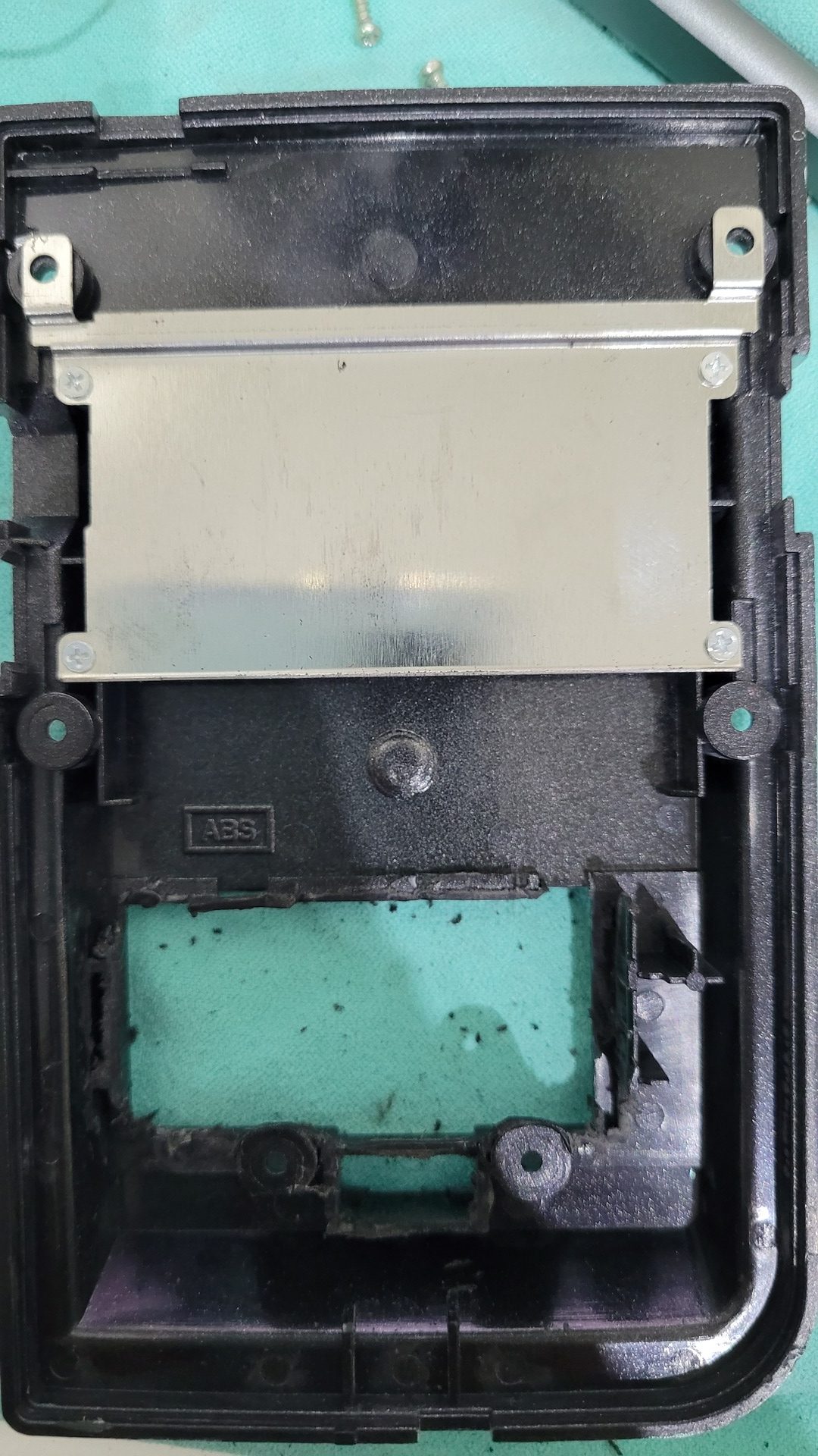
Shell mod
The original battery compartment must be removed so the lipo battery can fits correctly. It is a destructive mod, but regarding the price of a brand new shell, it’s not really a problem. The idea is to remove the batteries’ metal pad and spring, then cut the batteries’ plastic bed so the lipo battery can fits and the standard battery cover can stil be used. I used a pair of cutting pliers and a dremel cut the plastic.
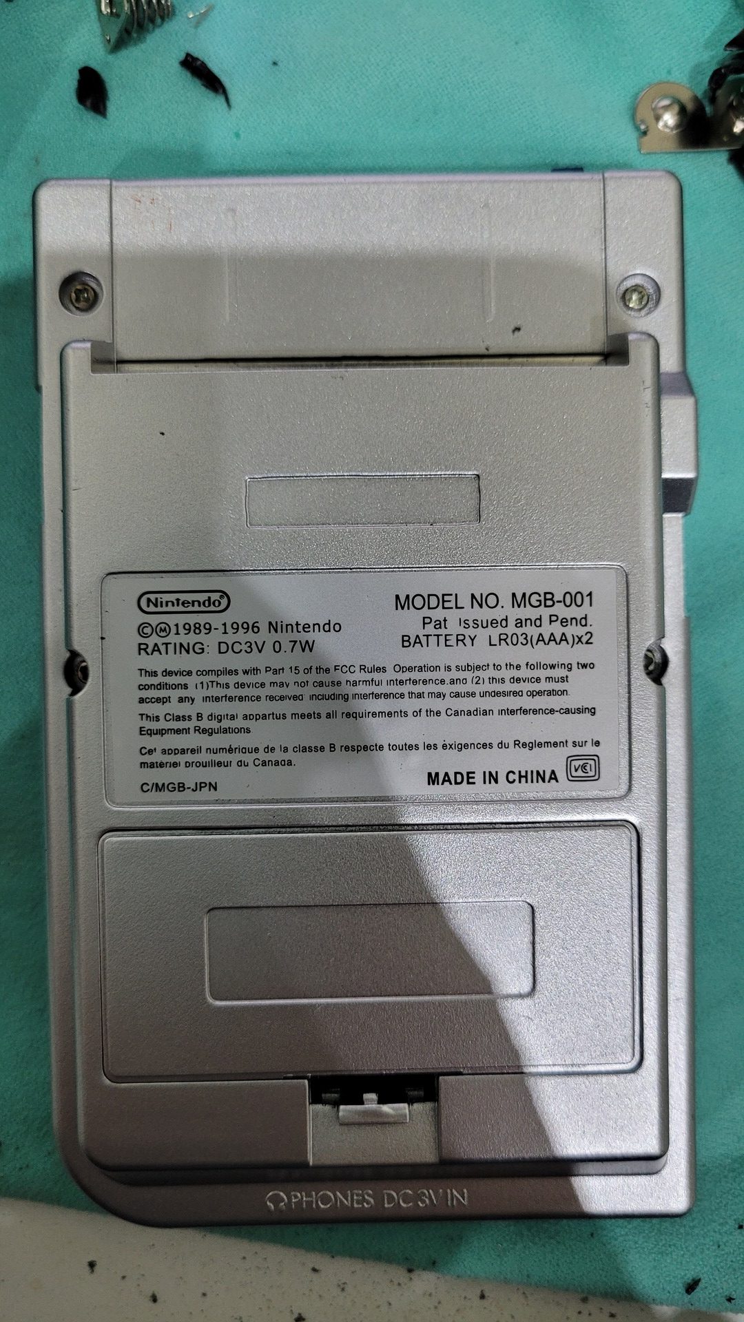
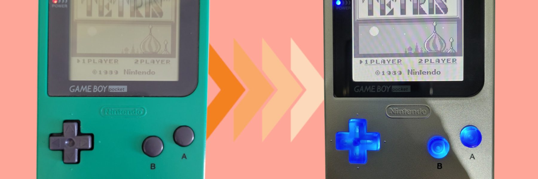
Results