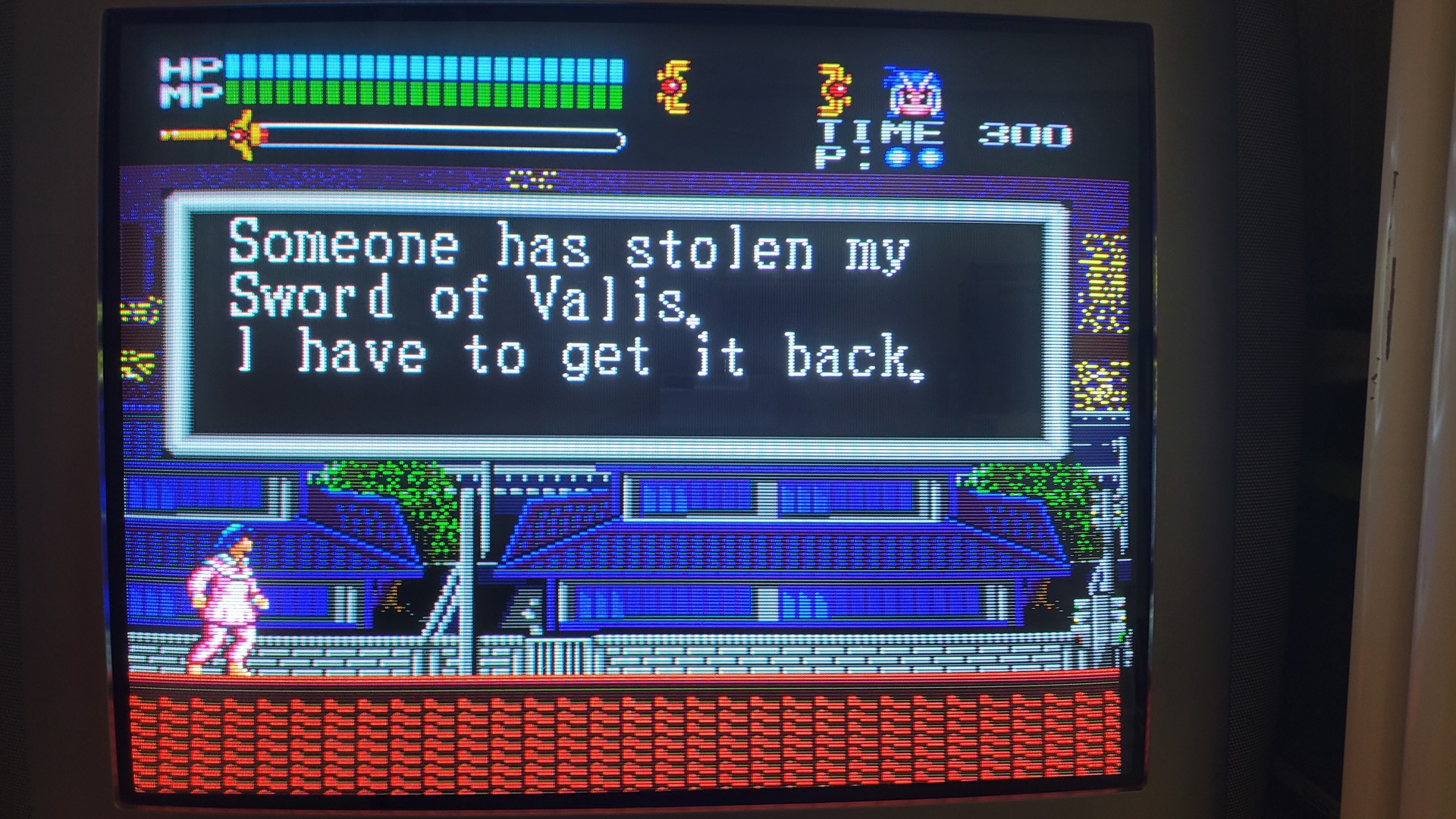
The video output of the original PC Engine DUO is composite only. Fortunately, the quality of its output is really good comparing to other consoles from the late 80′ / begining of 90′. But the signal is NTSC-J and if your display is not compatible, the picture will be in grey instead of colors. And that is the case of my old european CRT TV (a Grundig one). So I purchased an RGB kit from otakus-store and modded my DUO. The result is a nice and very sharp picture, but like many others I also had to fix the so called “jailbars” problem after this mod.
This is the story of my RGB modded DUO, following the otakus-store guide…
Needed materials
- A PC Engine DUO (Through, the otakus’s guide covers all PC Engine models)
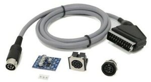
- An RGB kit from otakus-store
- Soldering flux
- Soldering iron with thin tip
- A continuity tester (optional, but regarding how tiny are the C6260 pins, no check = more risks)
- Some electrical tape
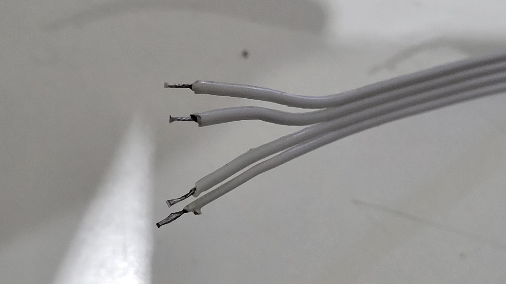
- Thin wires : I used an old ATA ribbon cable
- Tweezers

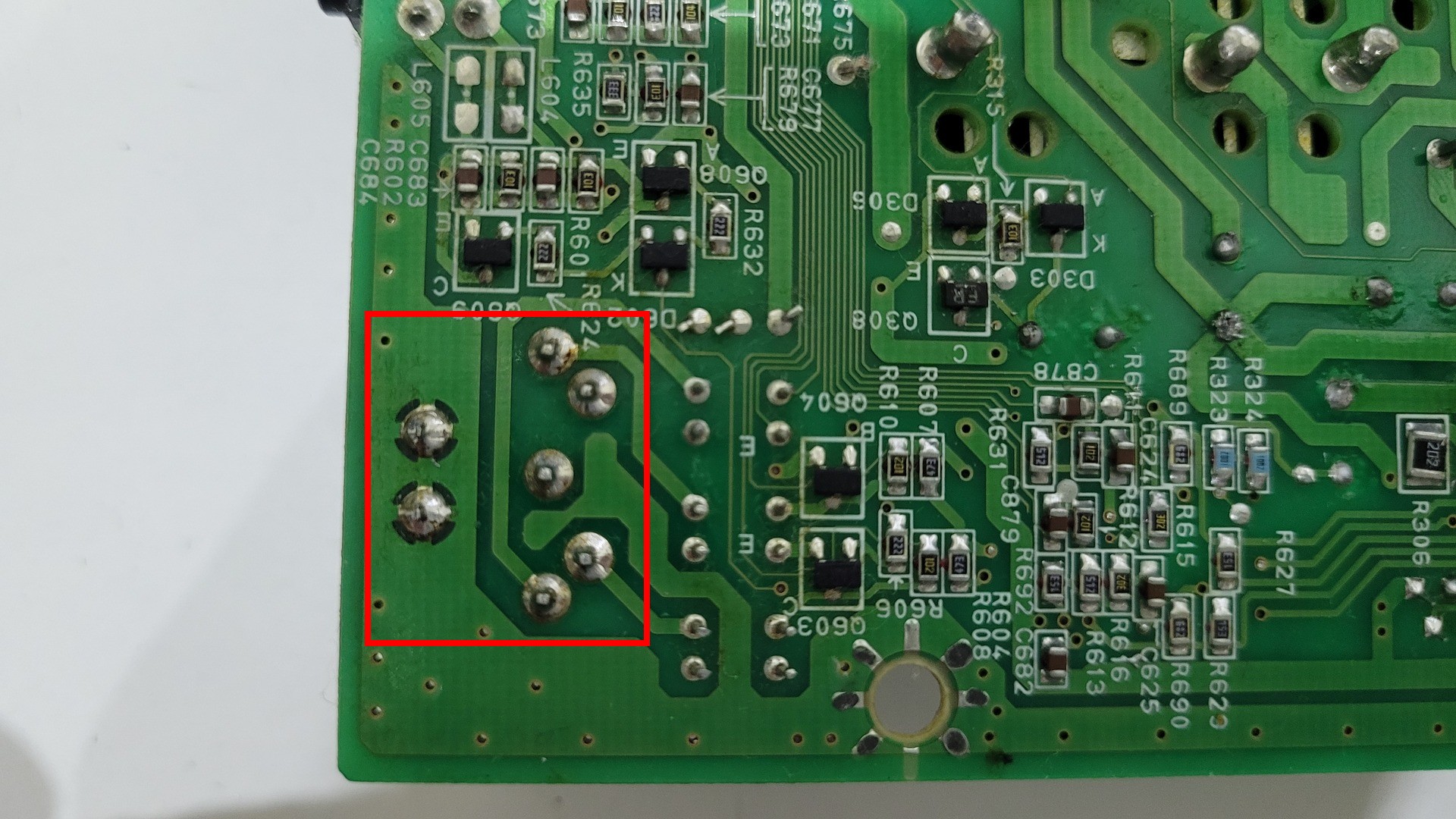
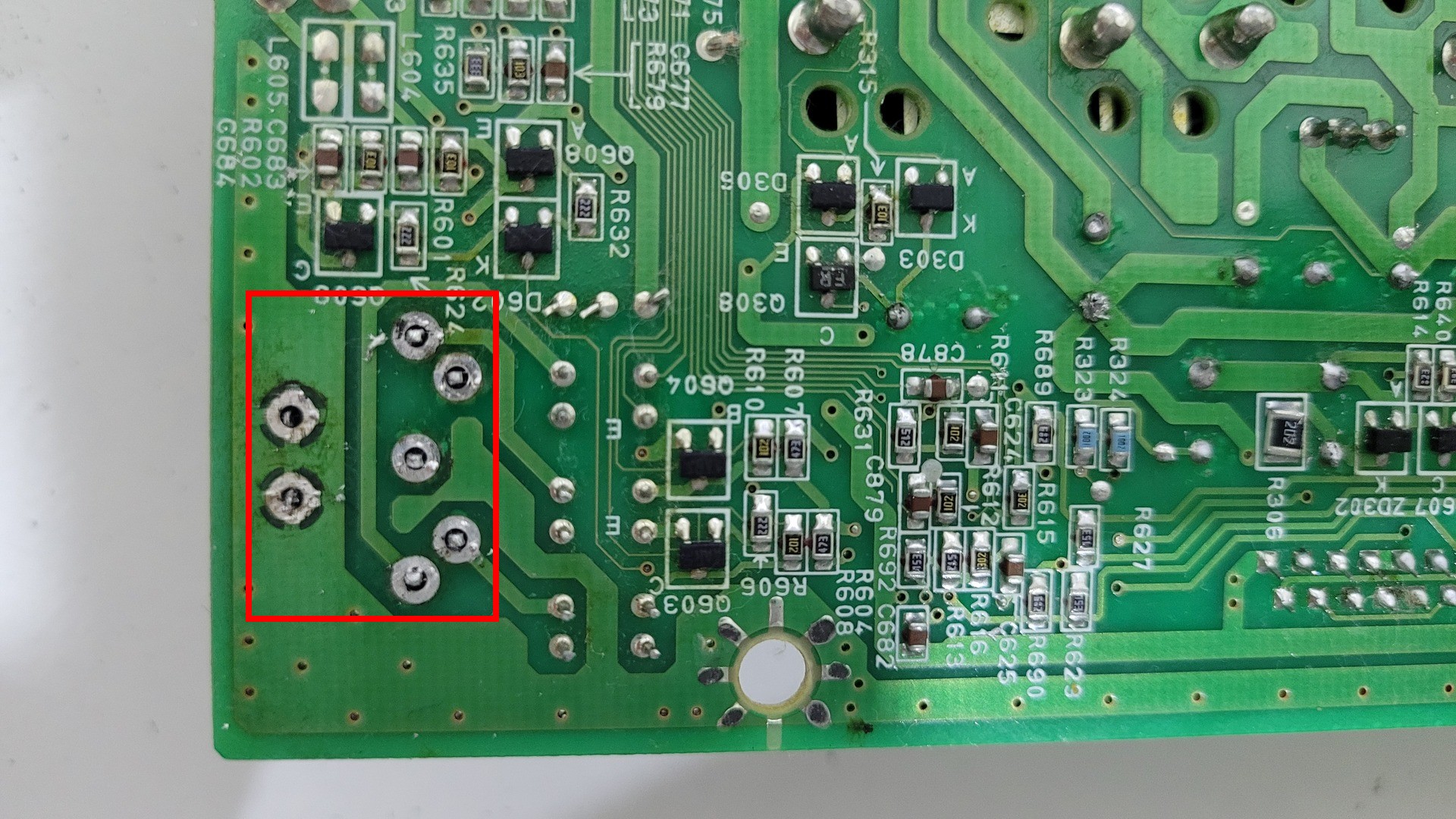
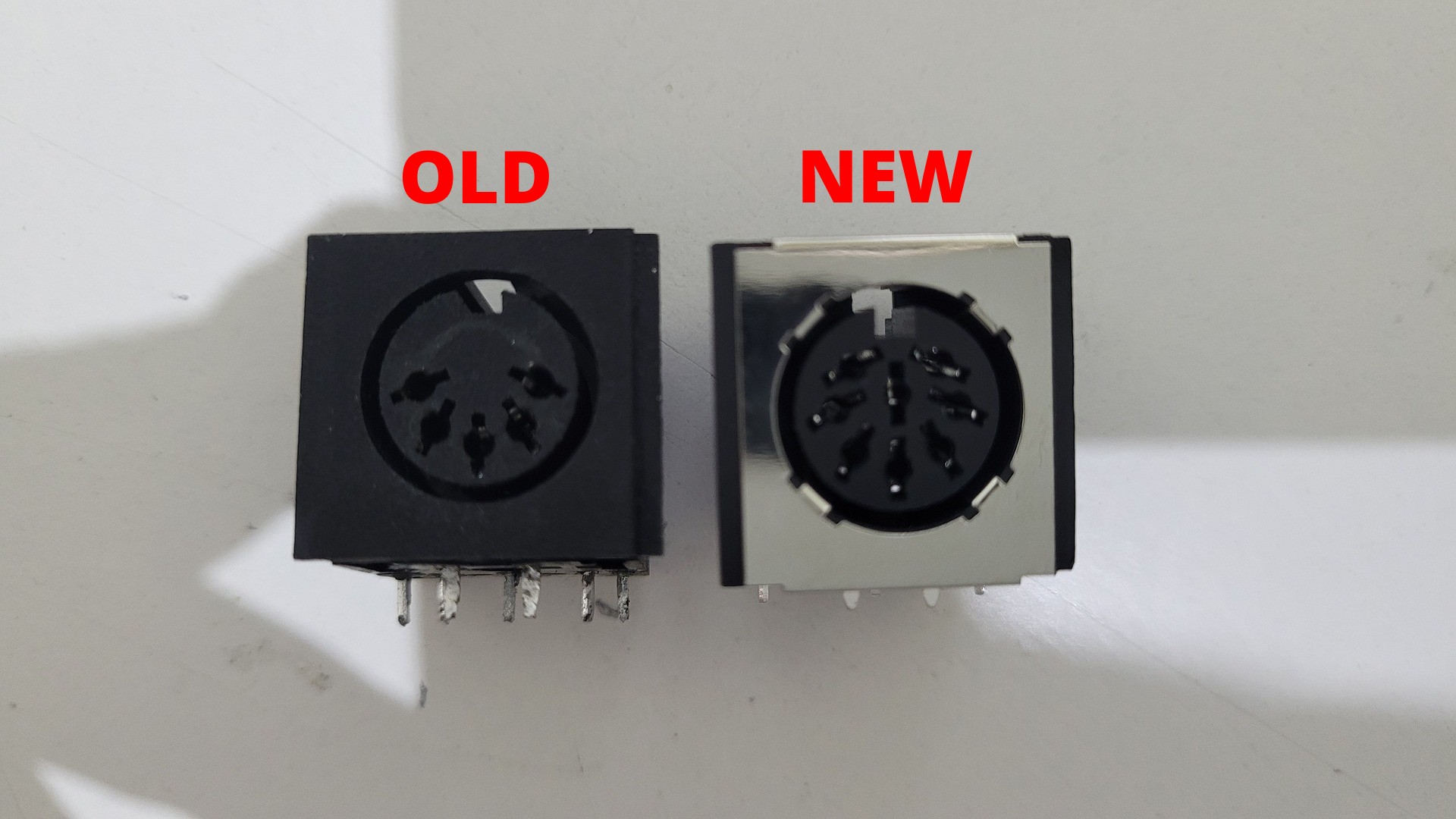
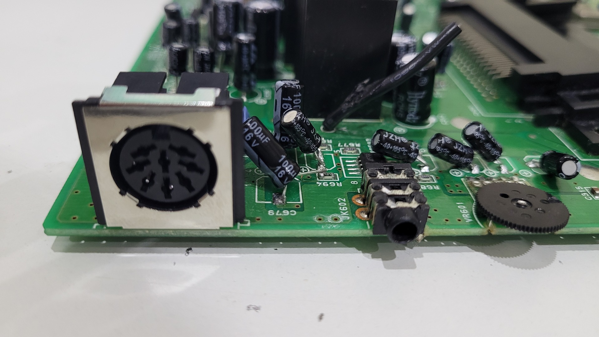
Replacing the video connector
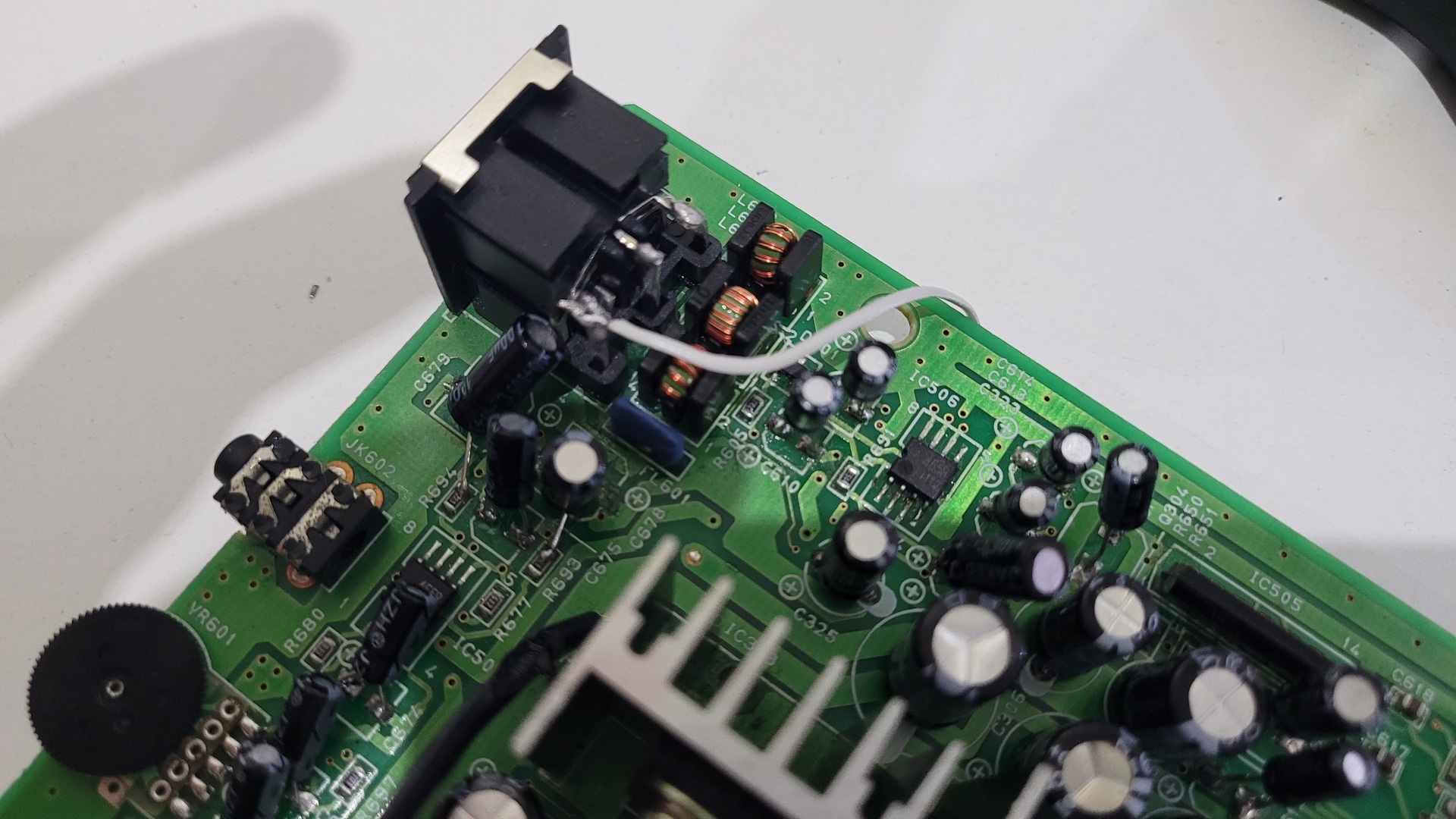
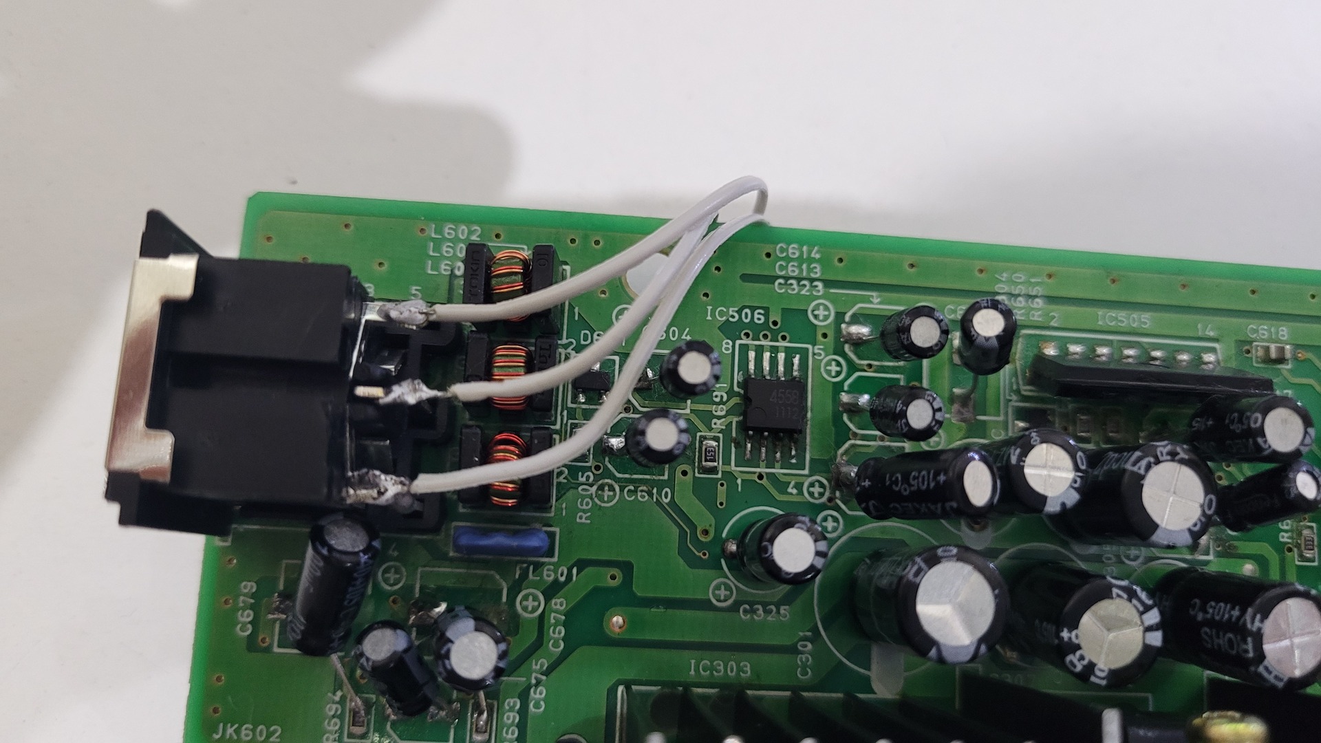
The original video connector must be replaced because it has only 5 connections whereas RGB output need 7 connections (R+G+B+Sync versus only one pin for composite). The kit comes with a modified 8 pins connector that can be soldered in the exact same place of the original one. The additional pins have been cut so they don’t block on the motherboard.
I used an desoldering pump to remove the connector, but I added some fresh solder before, just to help removing all the solder.

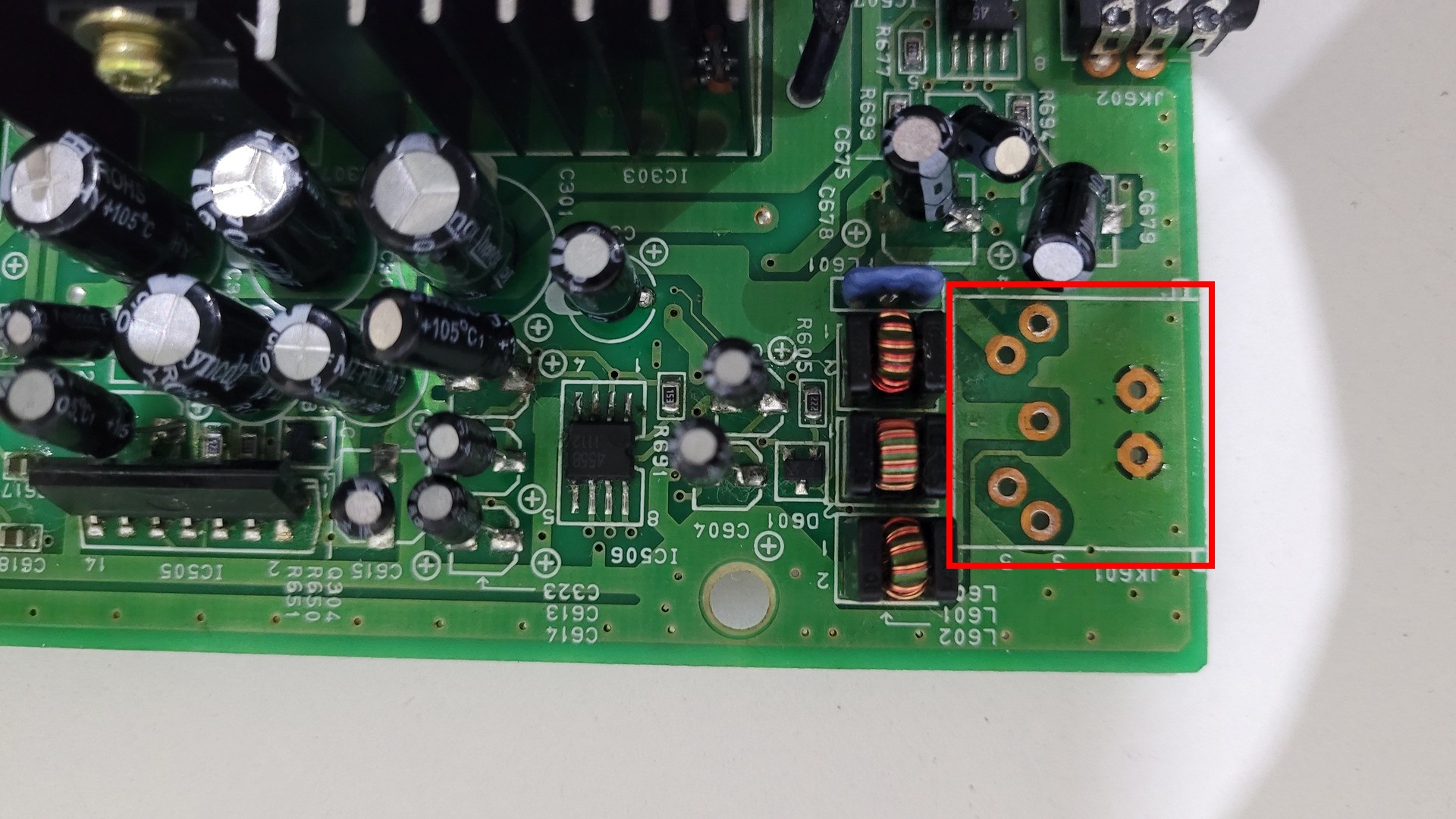
The new connector can be soldered directly.
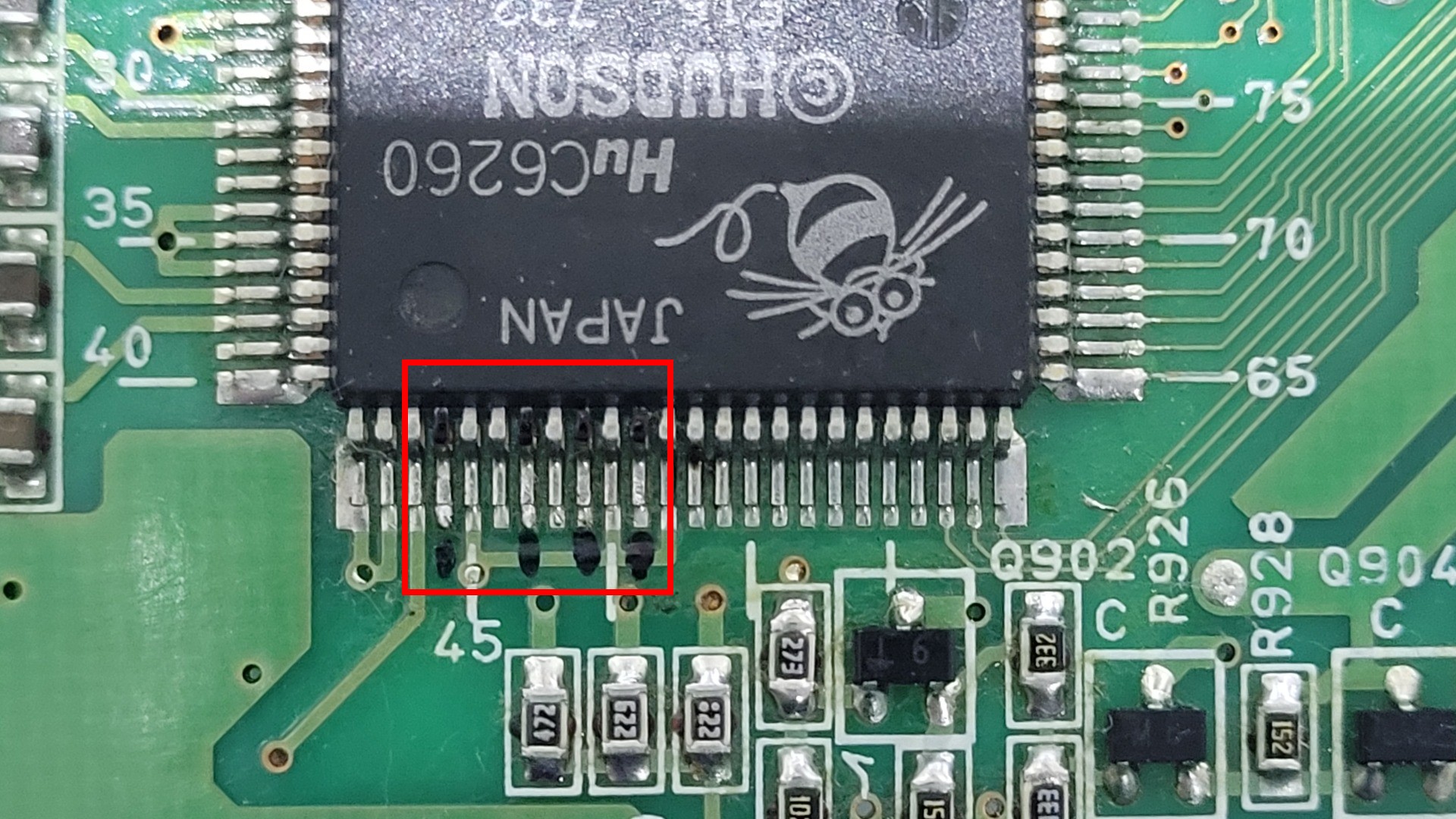
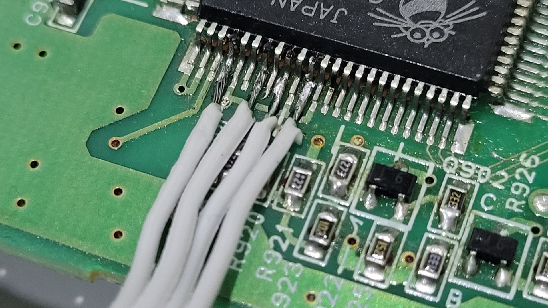
Adding wires to the C6260
This step is by far the most complicated. 4 wires must be soldered on the tiny legs of the C6260 chip (R, G, B and Csync). I marked the pins before starting as a foolproof. Then I added some solder on the target pins as well as on the wires before soldering them. I used a pair of tweezers to maintain the wires while applying the iron.
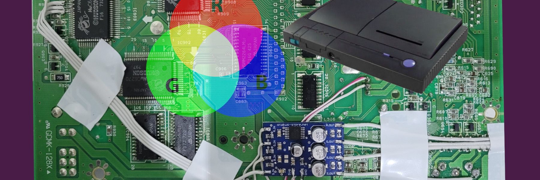
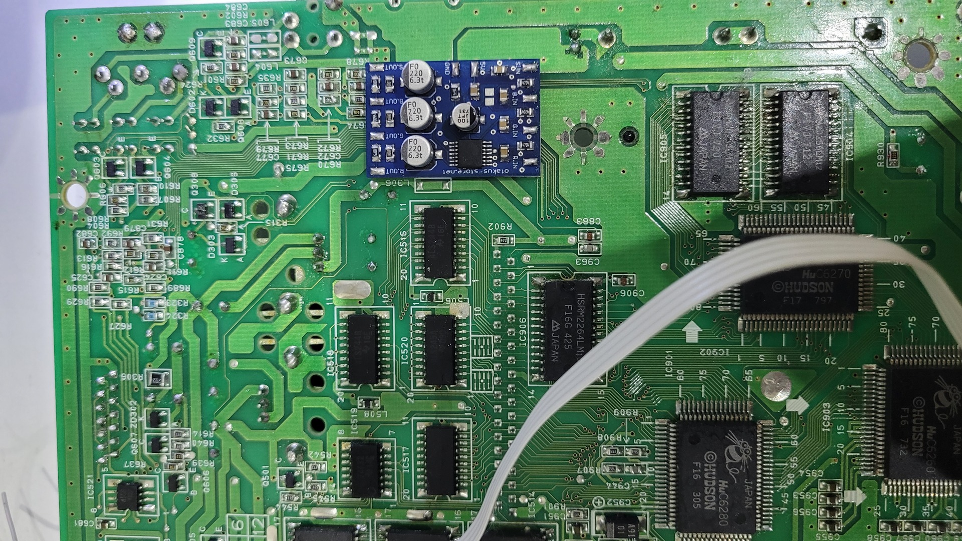
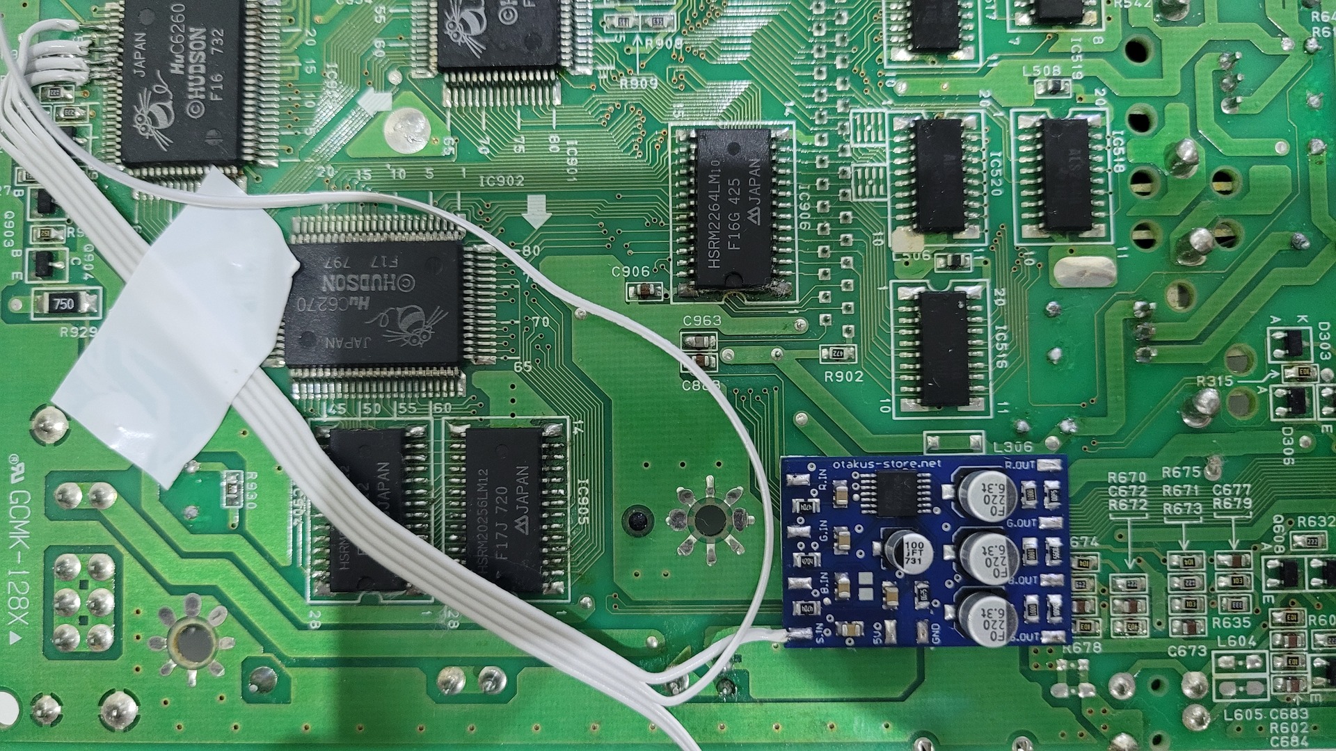
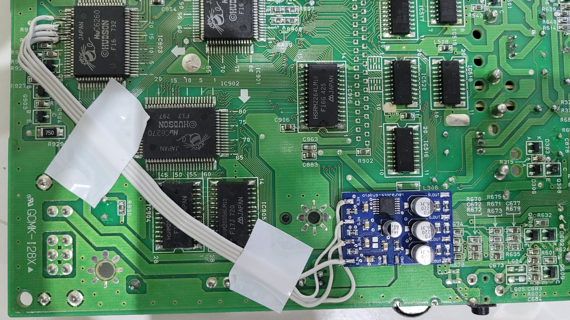
Wiring C6260 to RGB amp
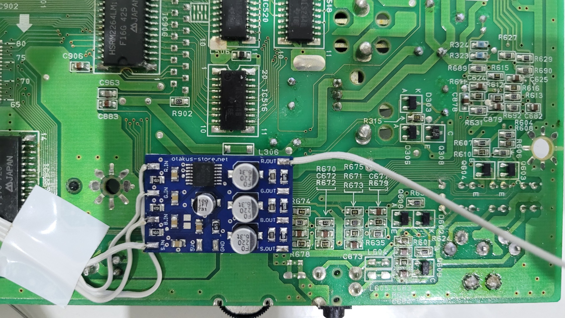
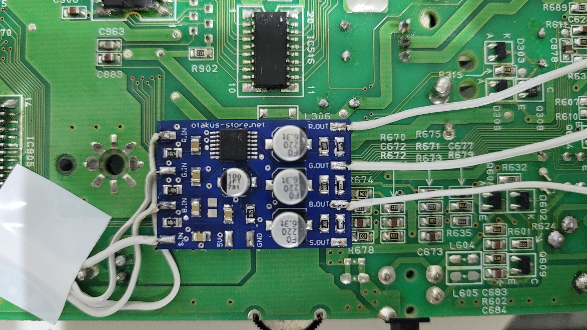
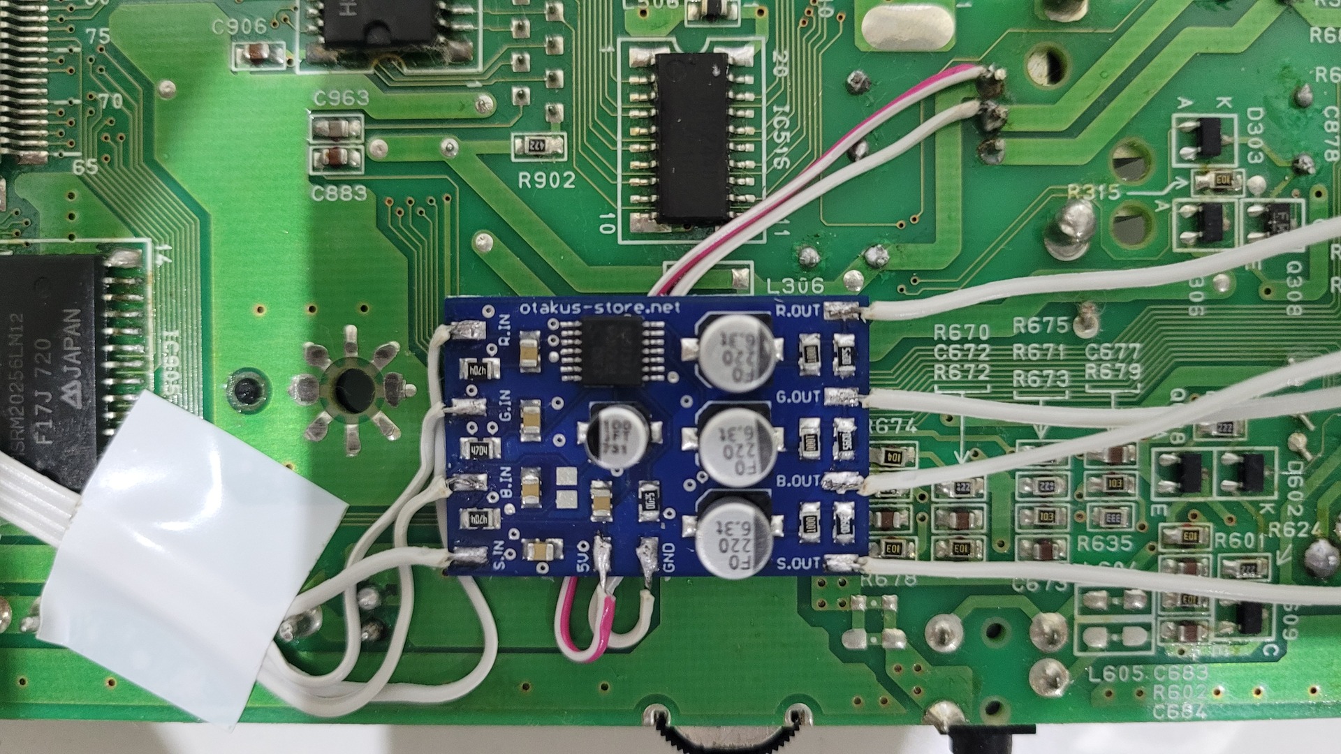
The RGB amp can be put on the back side of the motherboard. It comes with some double sided tape to fix it. I placed it next to IC516. I found this place ideal to keep the wires short.
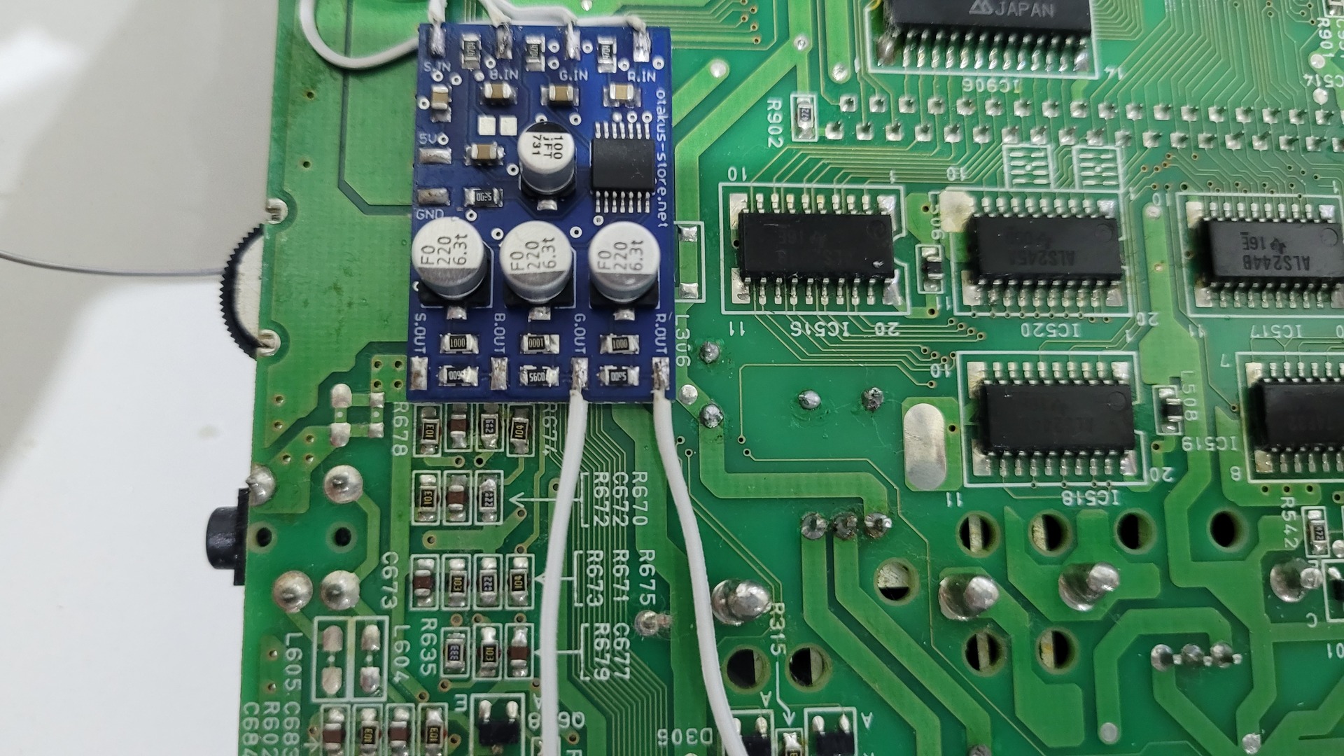
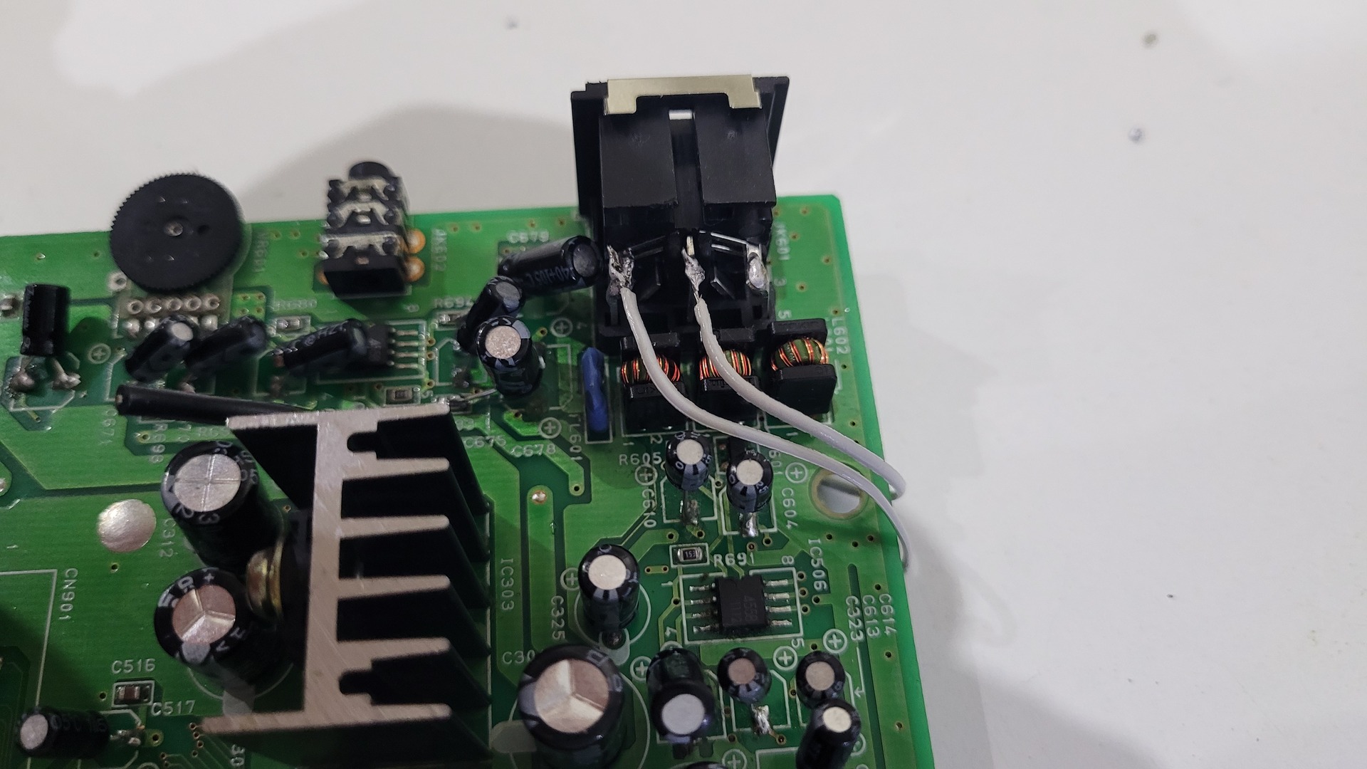
Wiring the RGB amp to video connector
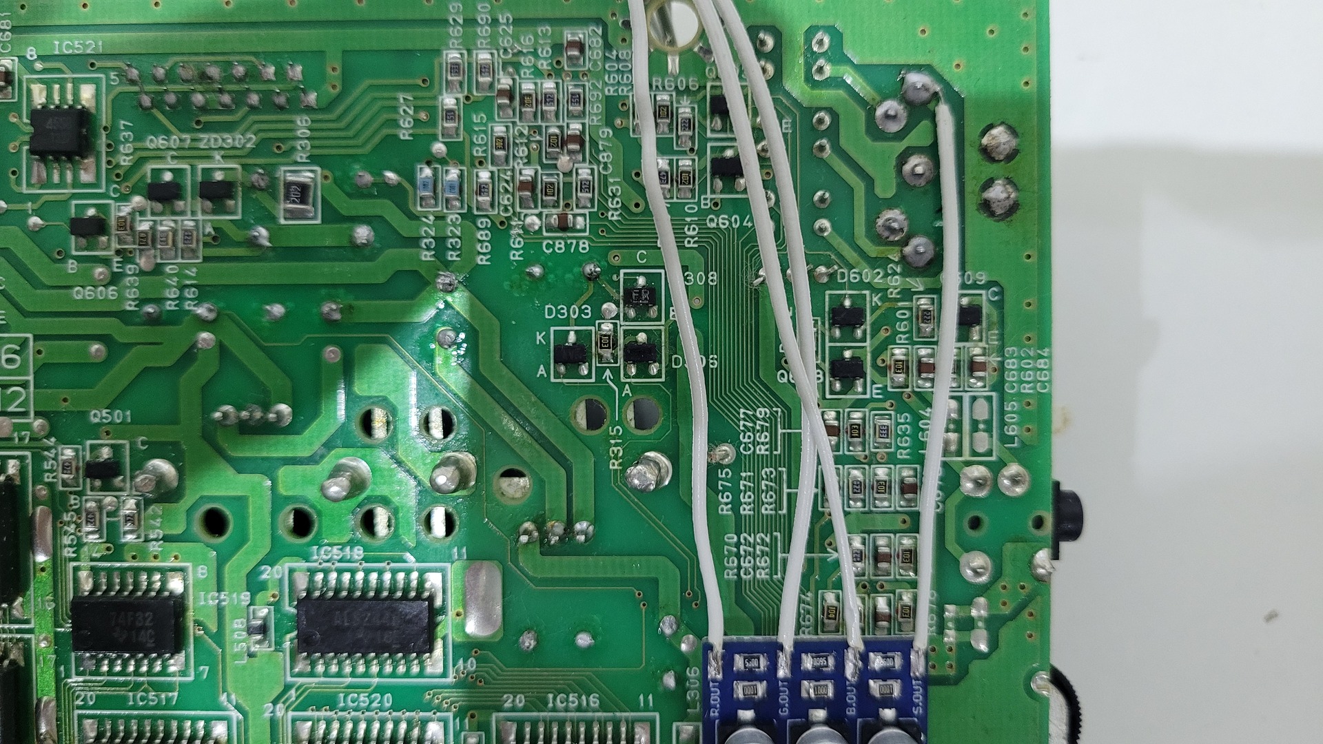
The RGB amp output have to be wired to the 3 additional pins of the new connector.
Wiring C-Sync signal
Some displays do not need this signal as they are able to use “sync on composite”. It is often, if not always, the case for european CRT: they do use the original composite signal as sync signal. However, this signal does not have a good quality because the same wire shares the whole composite signal which contains not only sync, but also color and luma.
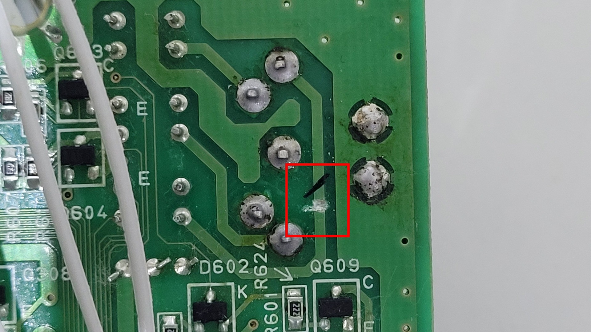
This step allows to provide the best possible sync signal : C-Sync, also called “Raw sync”. It provides V-Sync and H-Sync and makes the best possible picture out of the RGB signals. Beware that this step is destructive : it requires to cut a track on the motherboard and the composite signal will be completely lost (who cares ?)
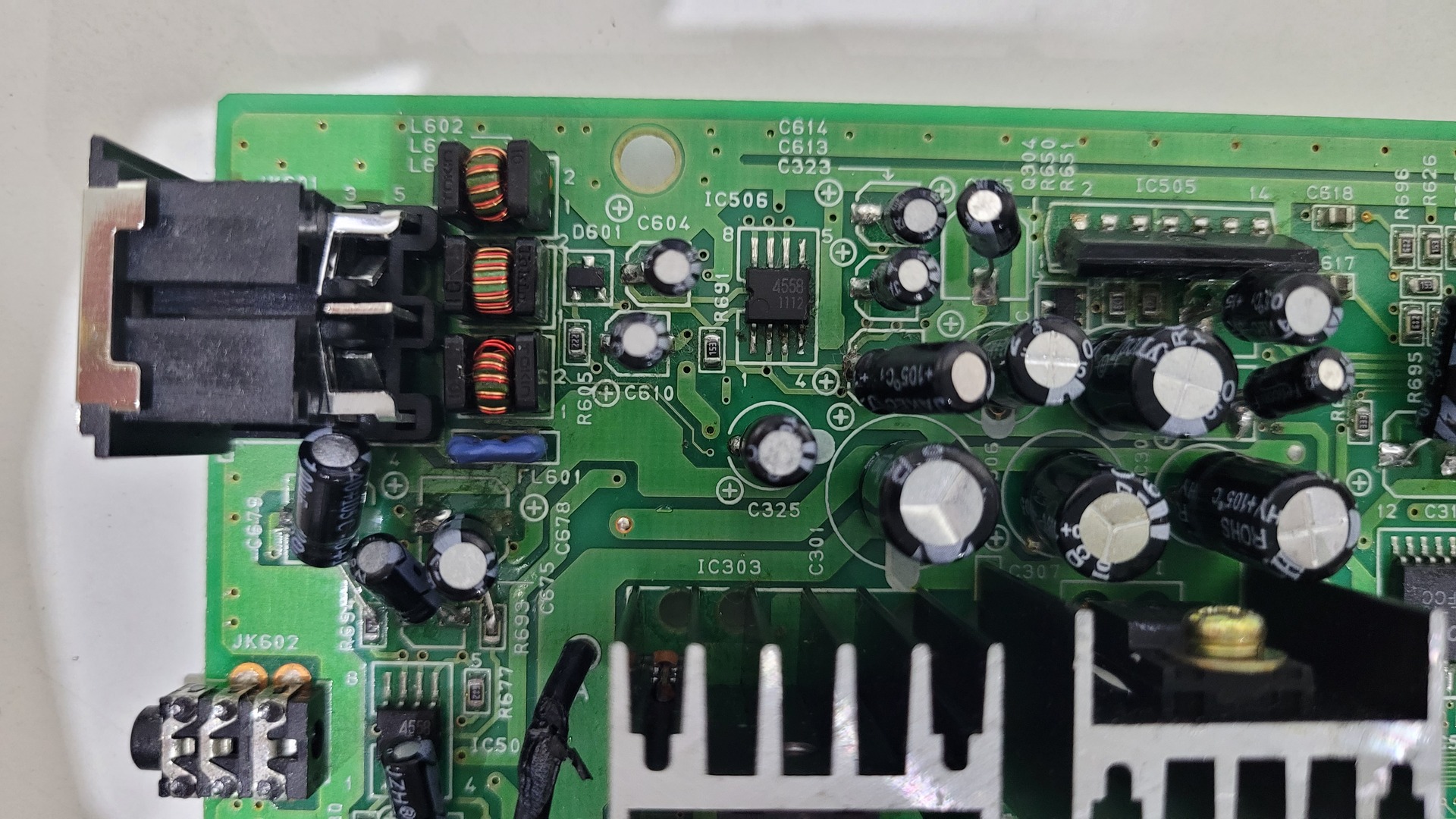
Powering the RGB amp
To finish up with the RGB output, the amp must be powered from a 5v source. I used two points near R315.
Jailbars fixing
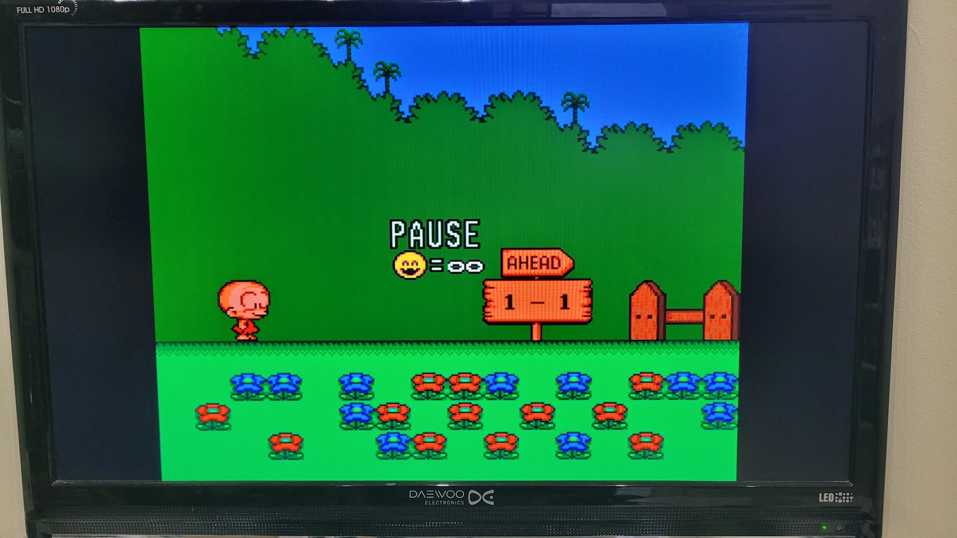
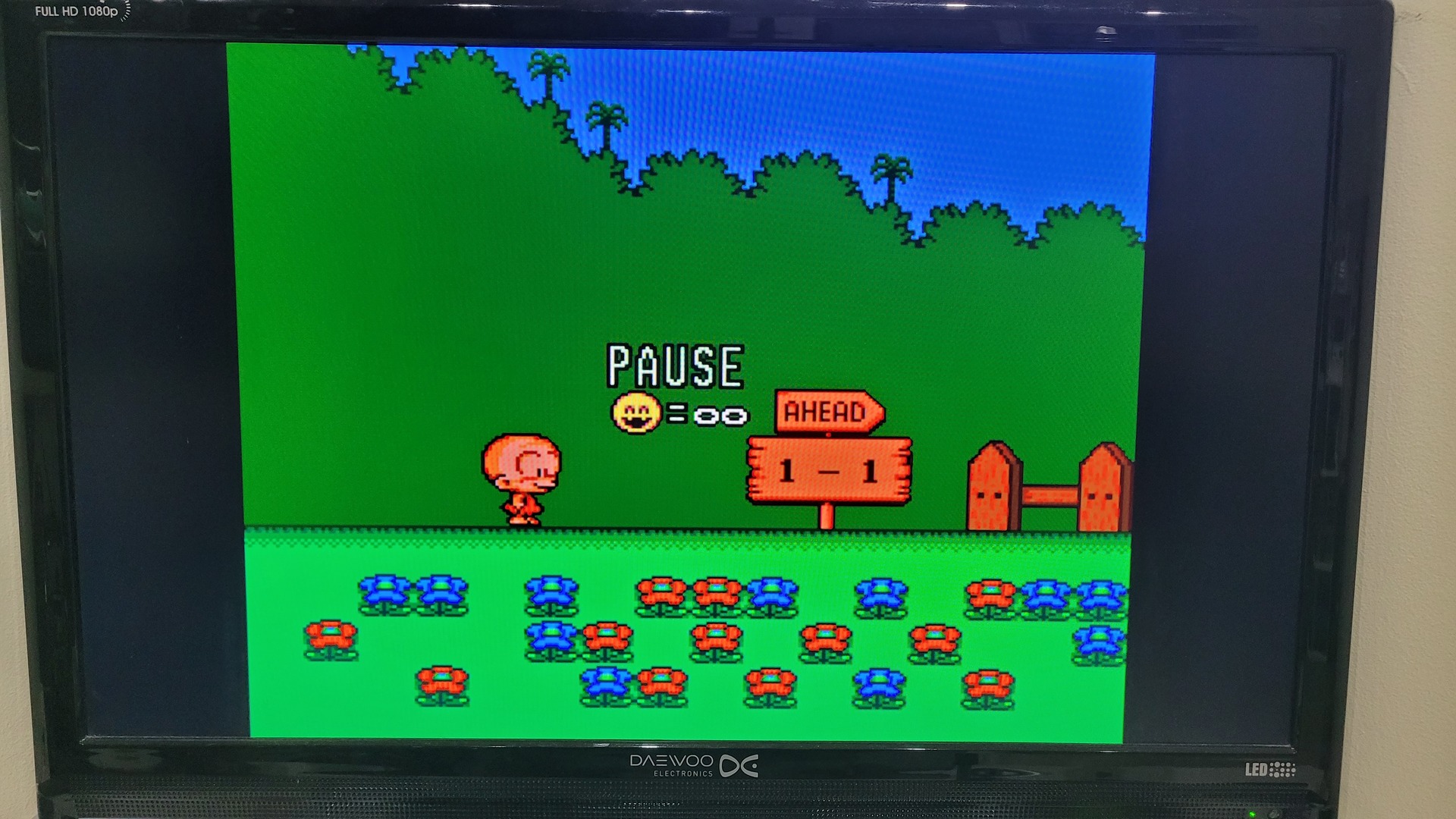
This step may not be needed, but on some console the RGB mod reveals another problem called “jailsbars”. The picture shows some slighly darker bars thar are more noticeable on plain flat colors. Here are some photos that show before (on the left) and after the fix (on the right)
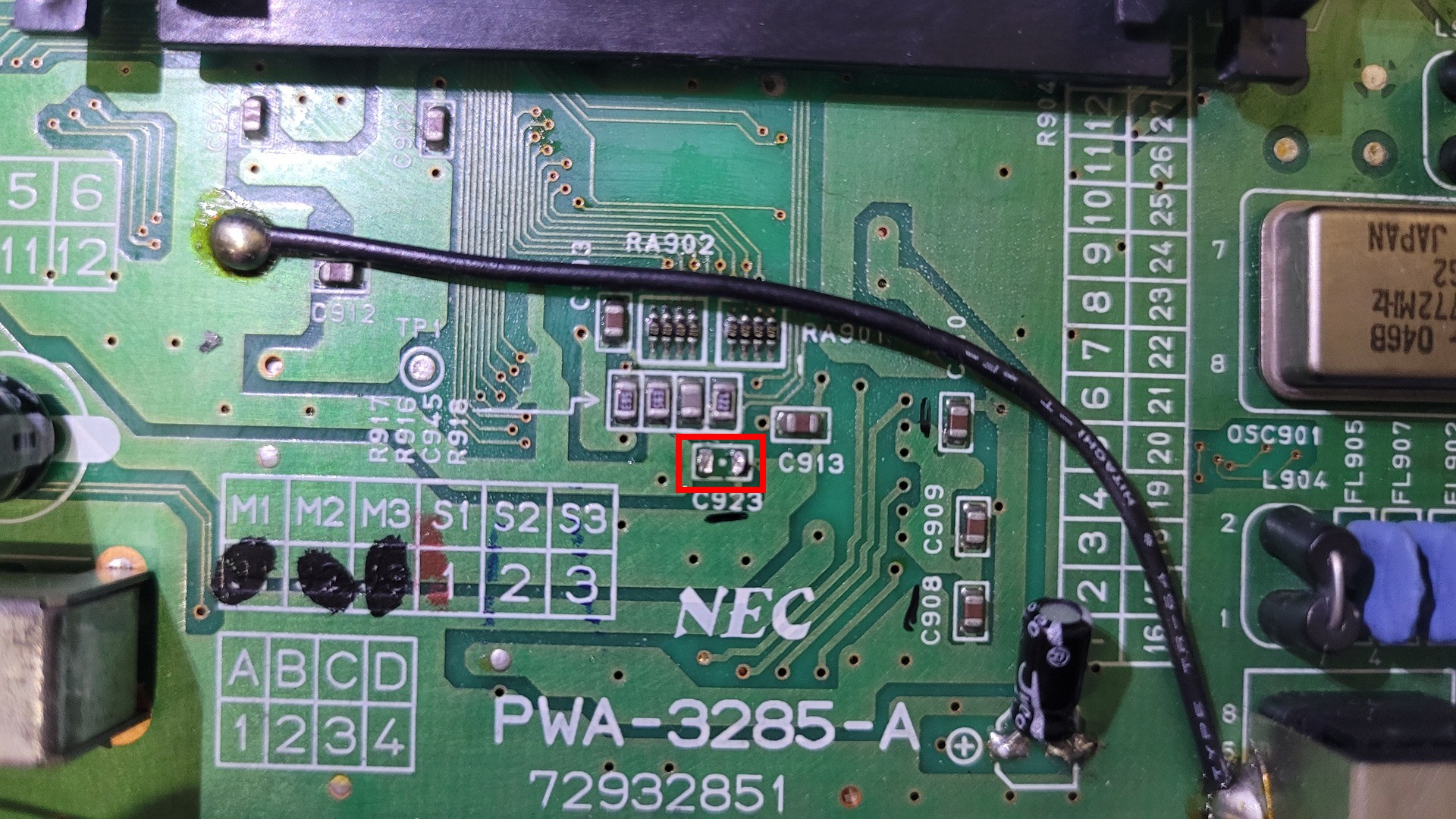
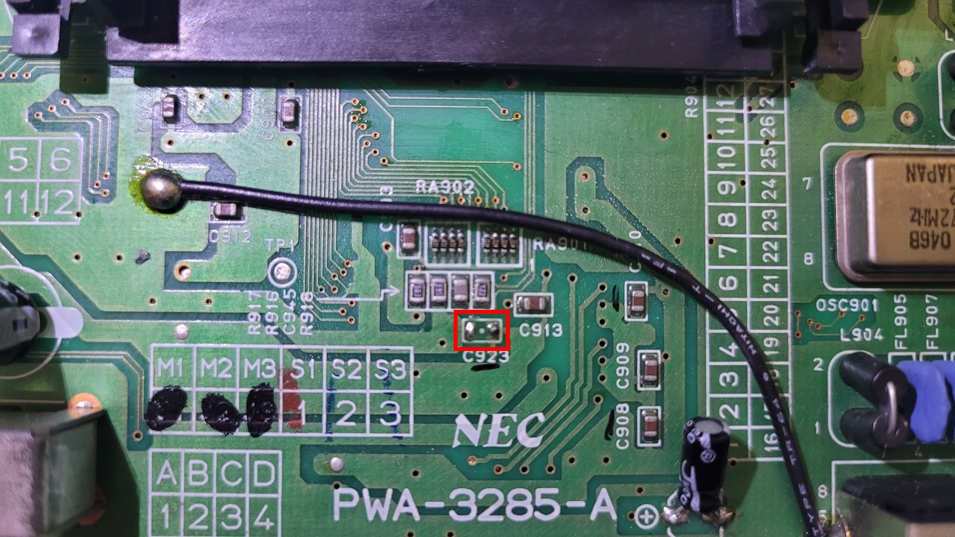
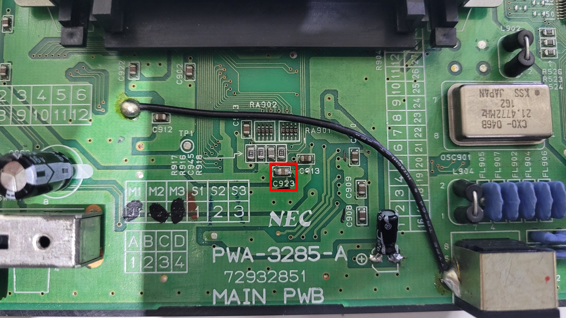
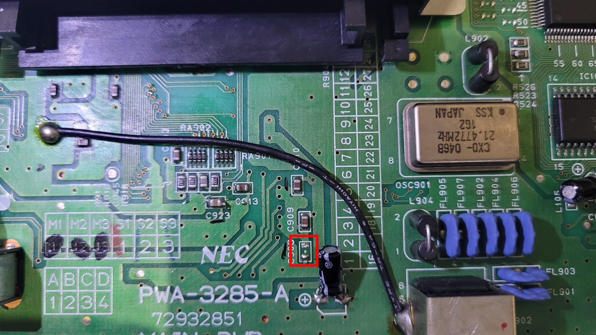
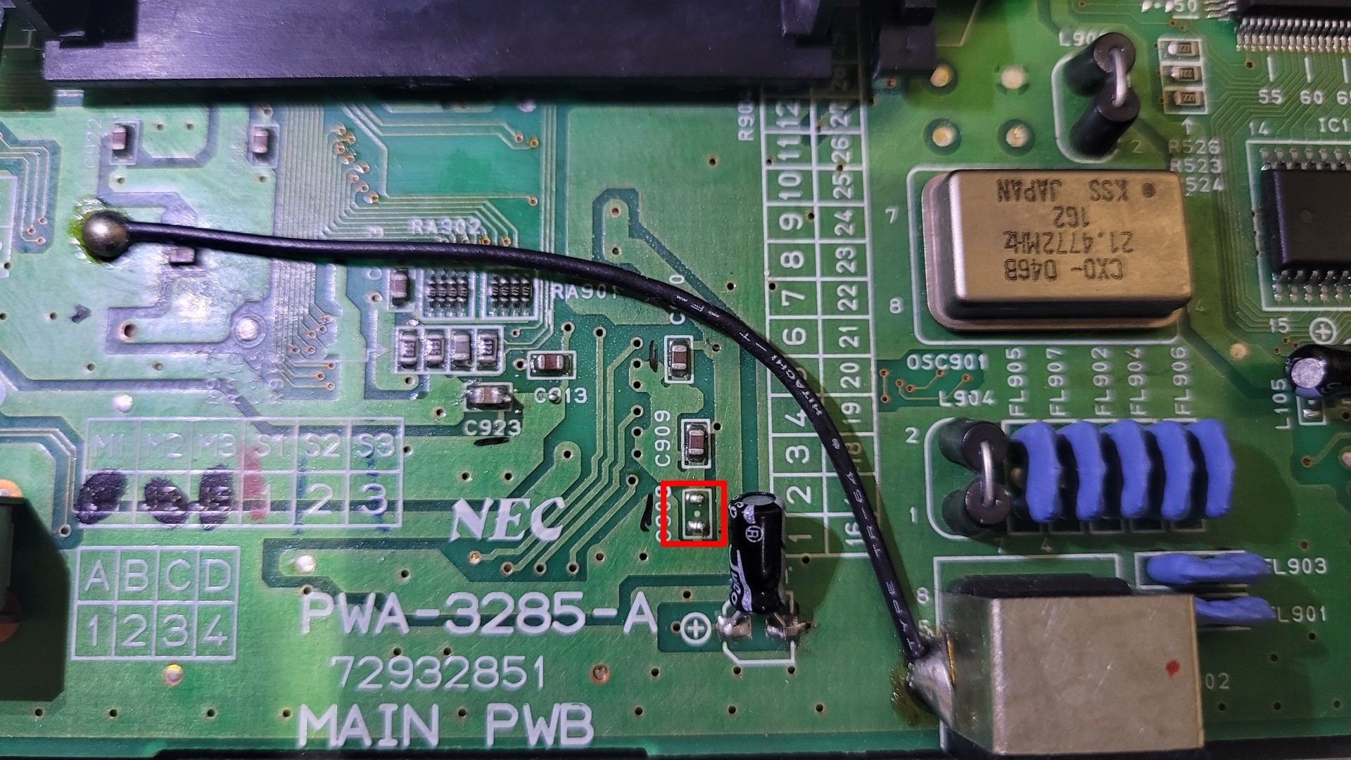
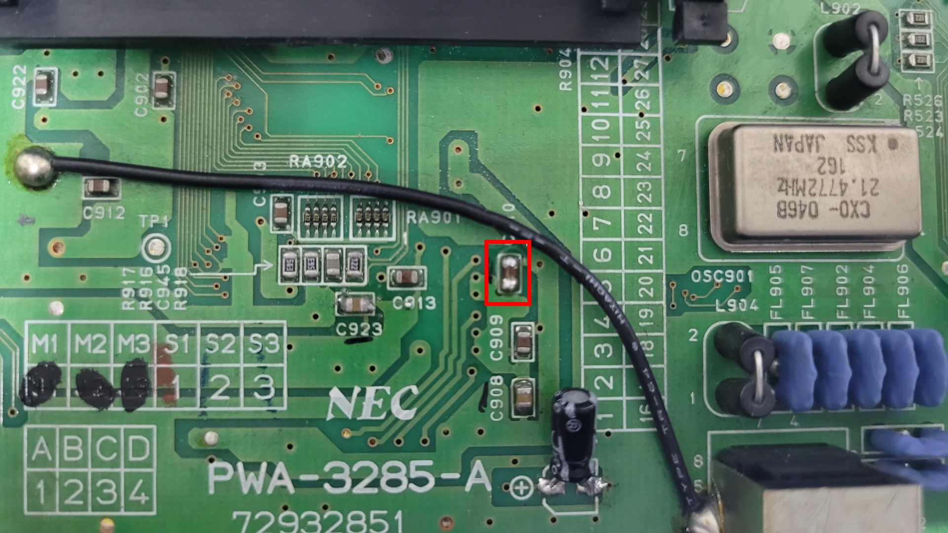
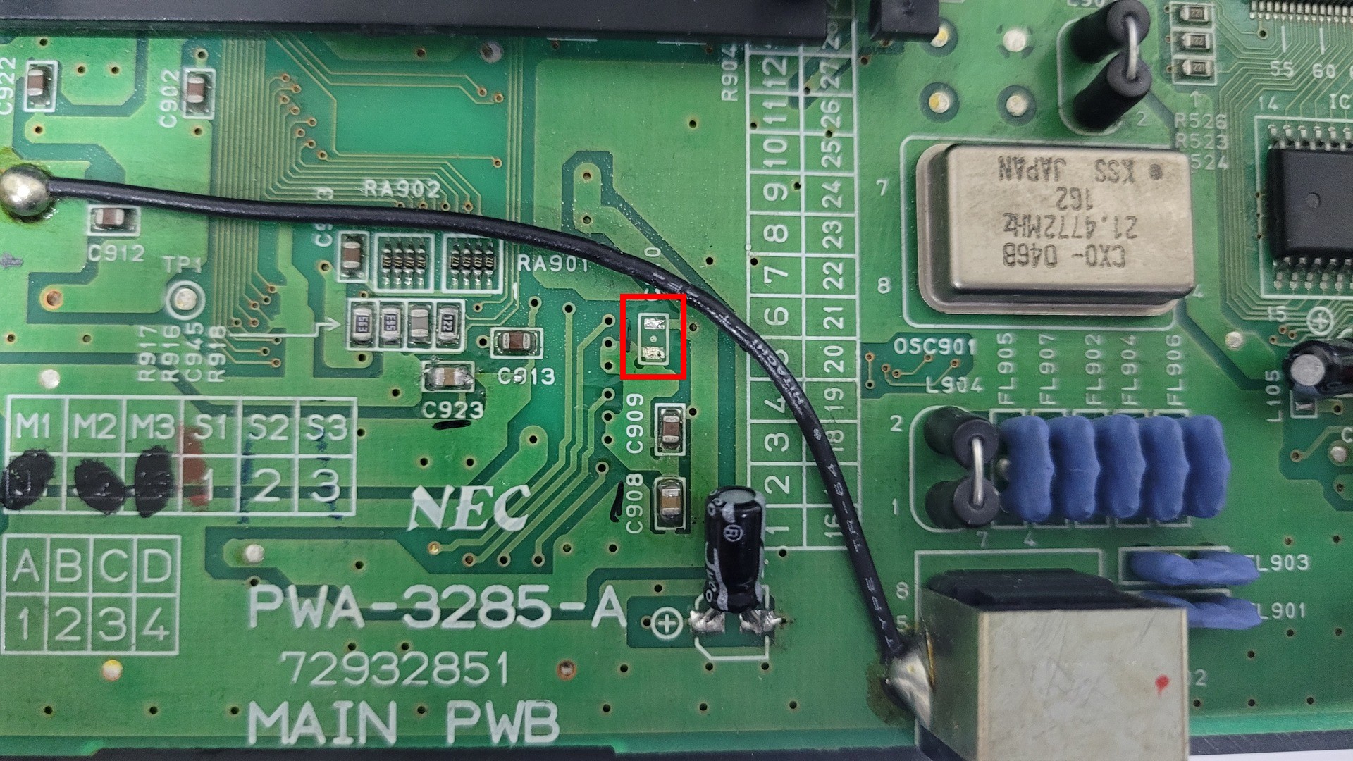
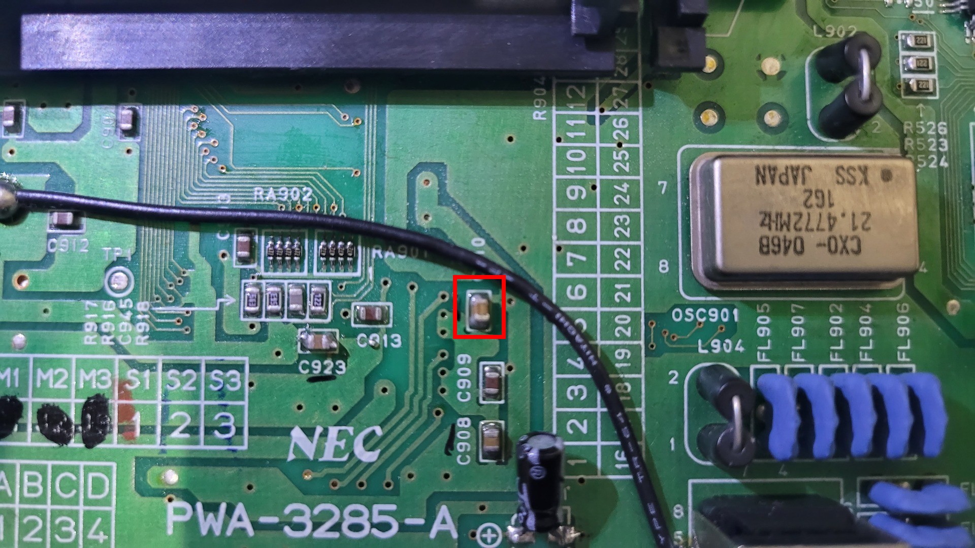
The fix consists in replacing 3 surface mounted non polarized capacitors. They are pretty small but not that hard to replace.
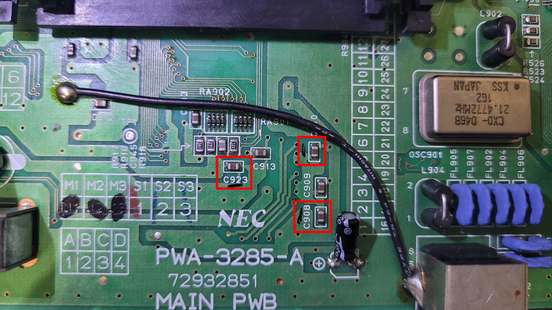
For each one I did like the following:
- Add some flux on each side of the capacitor
- Add some fresh solder
- Eat up both side at the same time while gently pushing the capacitor which, then, slides off it’s solder points
- Add some fresh solder on the two pads
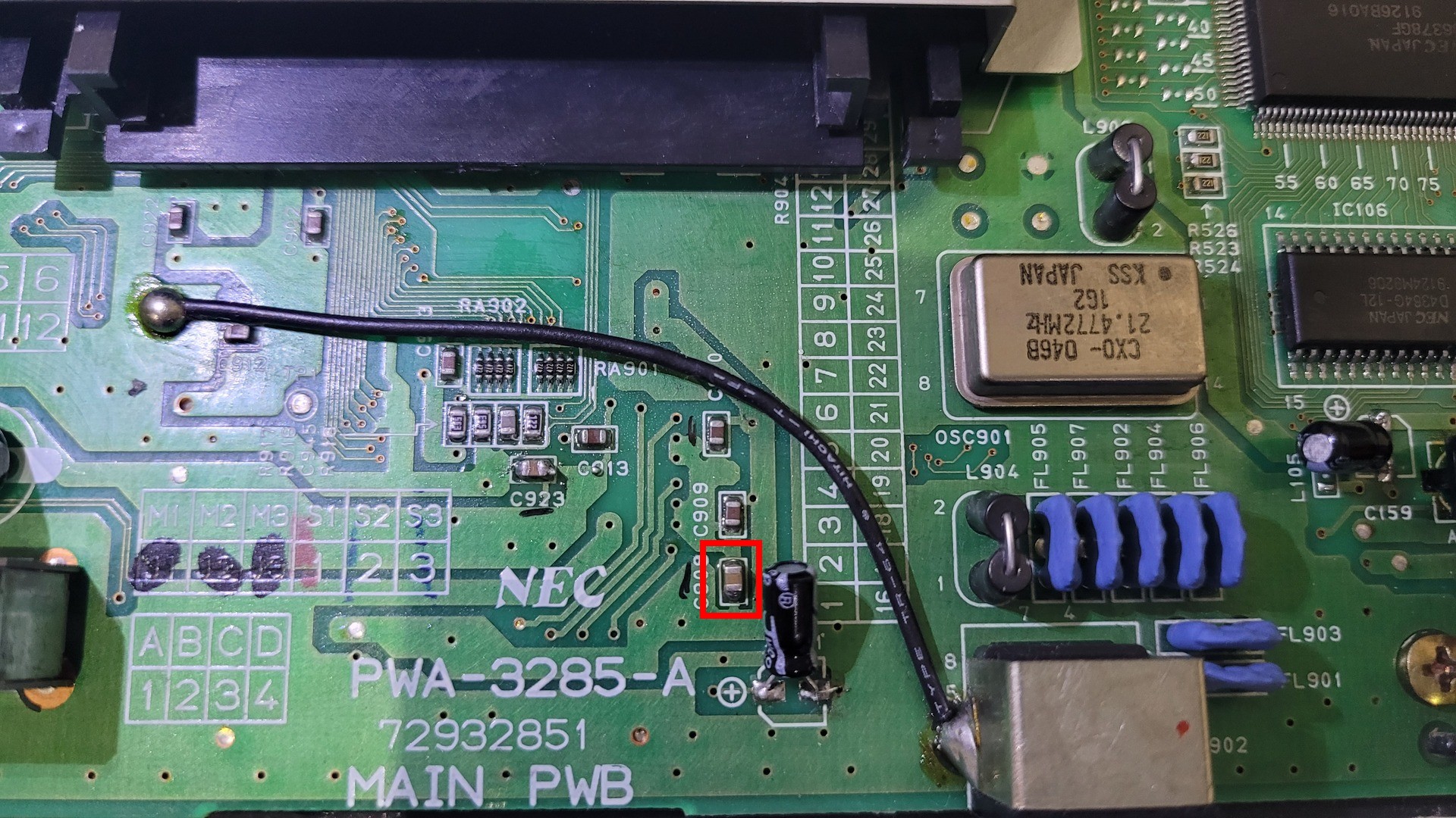
- Maintain the new capacitor with the a pair of tweezers while heating one side then the other
- Test that the display still works.
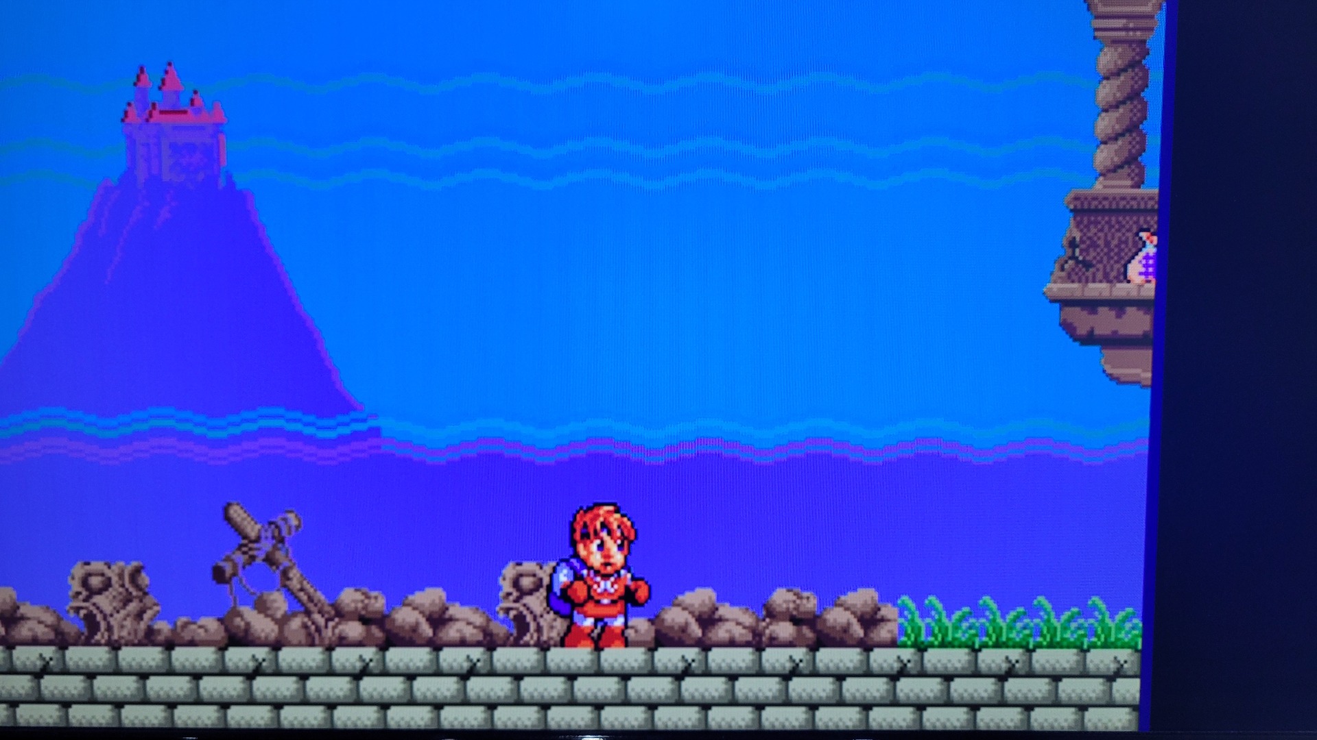
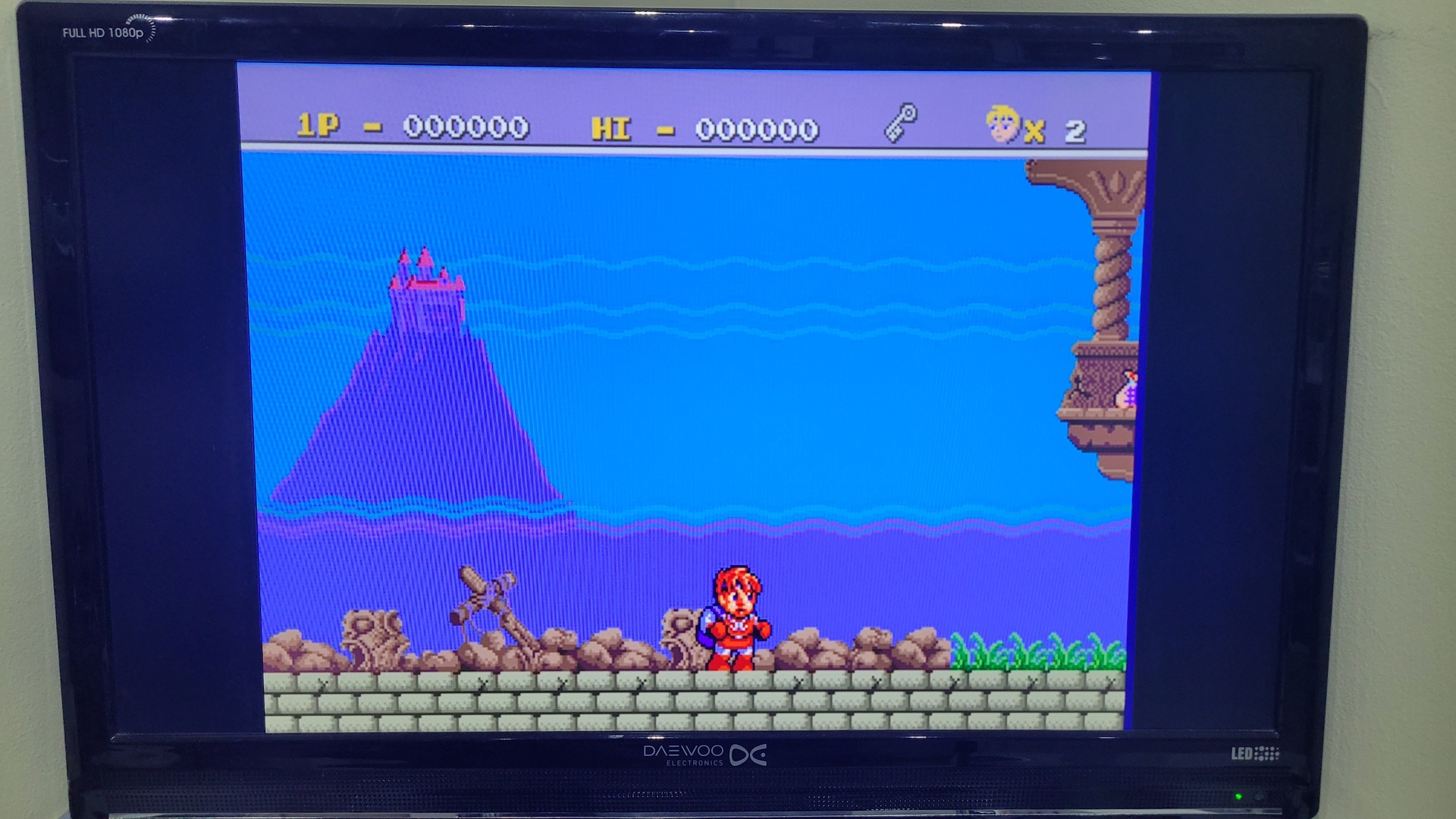
Result on a real CRT
And here is the final result on my good old Grundig european CRT TV