Despite the Megadrive has a quite fast processor for its time, the Motorola 68000, some games like Sonic 2 or Thunder force IV (and many others) suffer from slowdowns. It’s probably because the developpers tried to get more than the hardware is really capable of. Nevertherless, there is a good margin for improvement : the CPU is clocked at 7 Mhz and can easily be overclocked to 10 Mhz (even 12 Mhz on Megadrive 1). Fortunately, overclocking the CPU to 10Mhz is enough to make most (if not all) slowdown to disapear.
This is the story of my overclocked Megadrive 2…
Needed material
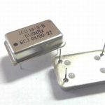
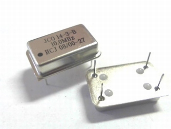
- A 4 pins 10 Mhz quartz oscillator (I used a rectangle one, but a square on should works if it’s 5v tolerent)
- Some thin wires, like those found on old ribbon cables (floppy or IDE / P-ATA)
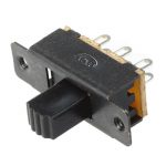
- A 2 positions switch (3 pins)
- A simple switch that could be momentary (2 pins)
- Some flux and thin solder wire
- A dremel
- Flat small file
- A drill

Umounting motherboard
Removing the motherboard is pretty easy, and I have already coverred that the a previous article about a switchless region mod.
Motherboard modding
Overview
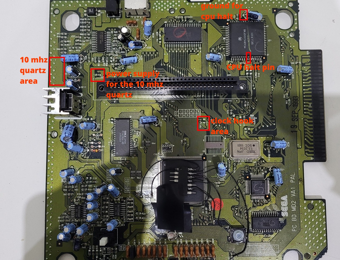
Here is an overiew of all zones of the motherboard I have worked on.
Basicaly, we need to intercept the original clock signal and bring it to a switch. This switch will also be wired to the new 10Mhz quartz, so it will be possible to switch between the original 7Mhz and the new 10 Mhz oscillator.
In addition, by using another switch that momentaneously connect the ground to the pin 19 of the CPU, the CPU enters in “halt” mode. Putting the CPU in “halt” mode is mandatory to change the frequency while the console is running. However this feature is optional because the frequency can be chosen before turning the console on. However it may be needed to boot in 7Mhz then switch to 10Mhz while the console runs. For example, some flash cartridges won’t launch a game if the CPU is not running at the original frequency but will run perfectly fine after the game as been loaded (the flashing process may corrupt the game if not done at 7Mhz).
CPU Halt
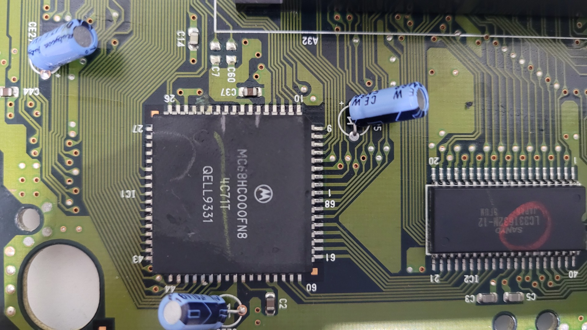
Halting the execution flow of the Motorola 68000 is easy : just put the pin 19 to ground. It’s like pausing the console (except sound and music that are driven by the Z80 CPU).
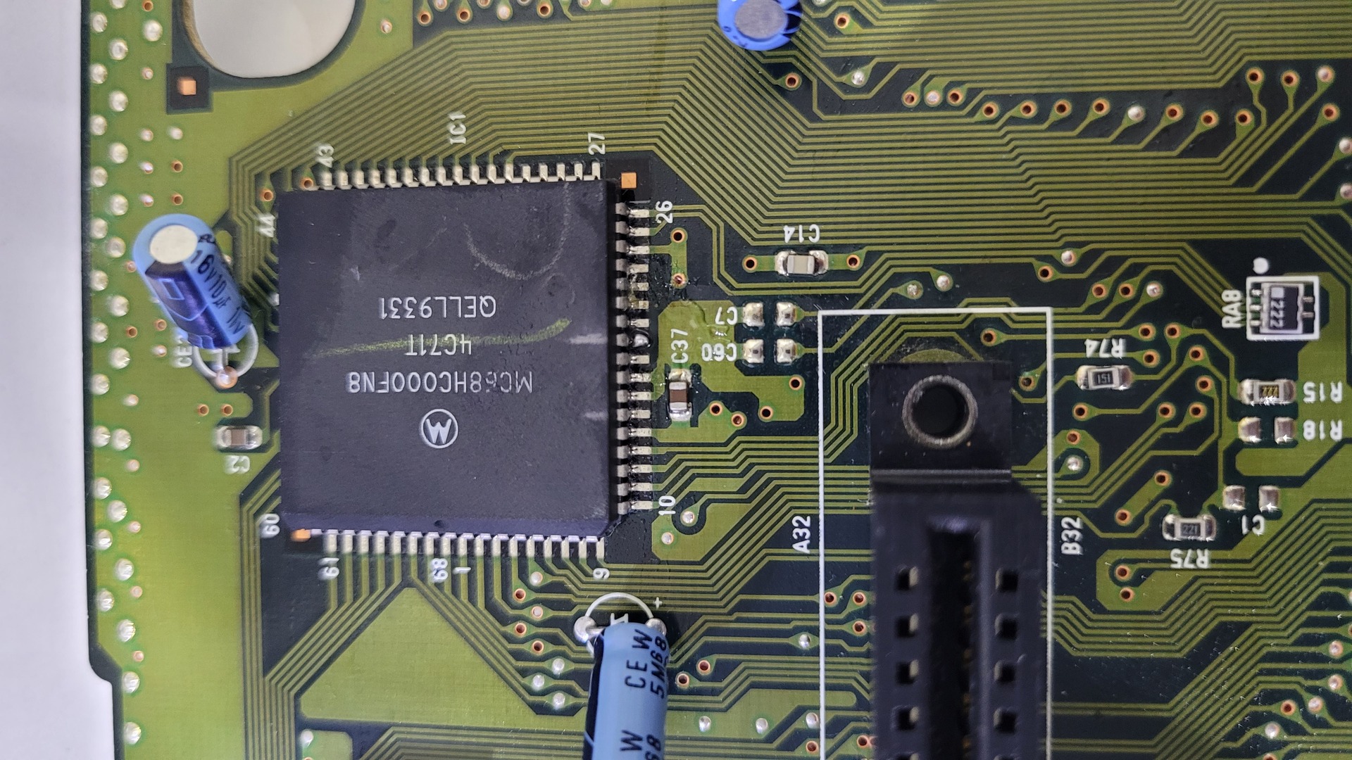
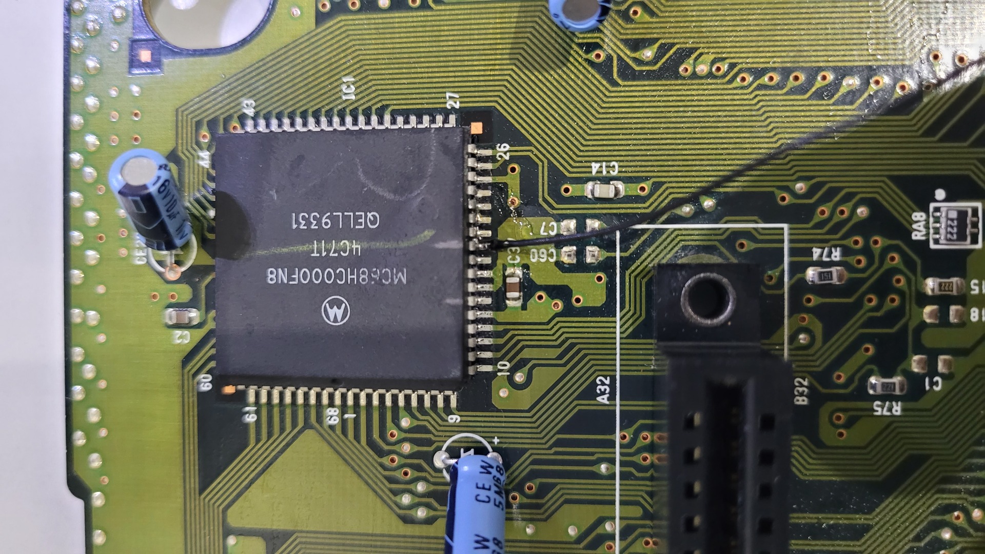
I used some flux to make soldering easier. Below are photos of the cpu before the modification, the cpu with some flux plus solder on pin 19 and the cpu with the wire soldered:
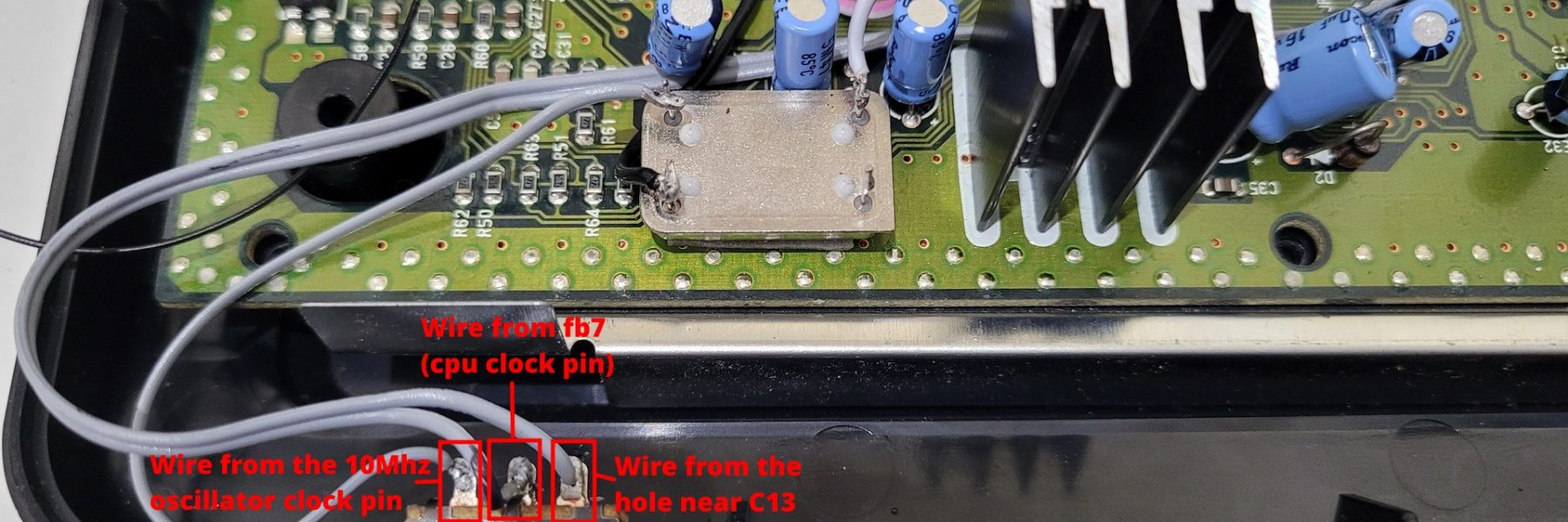
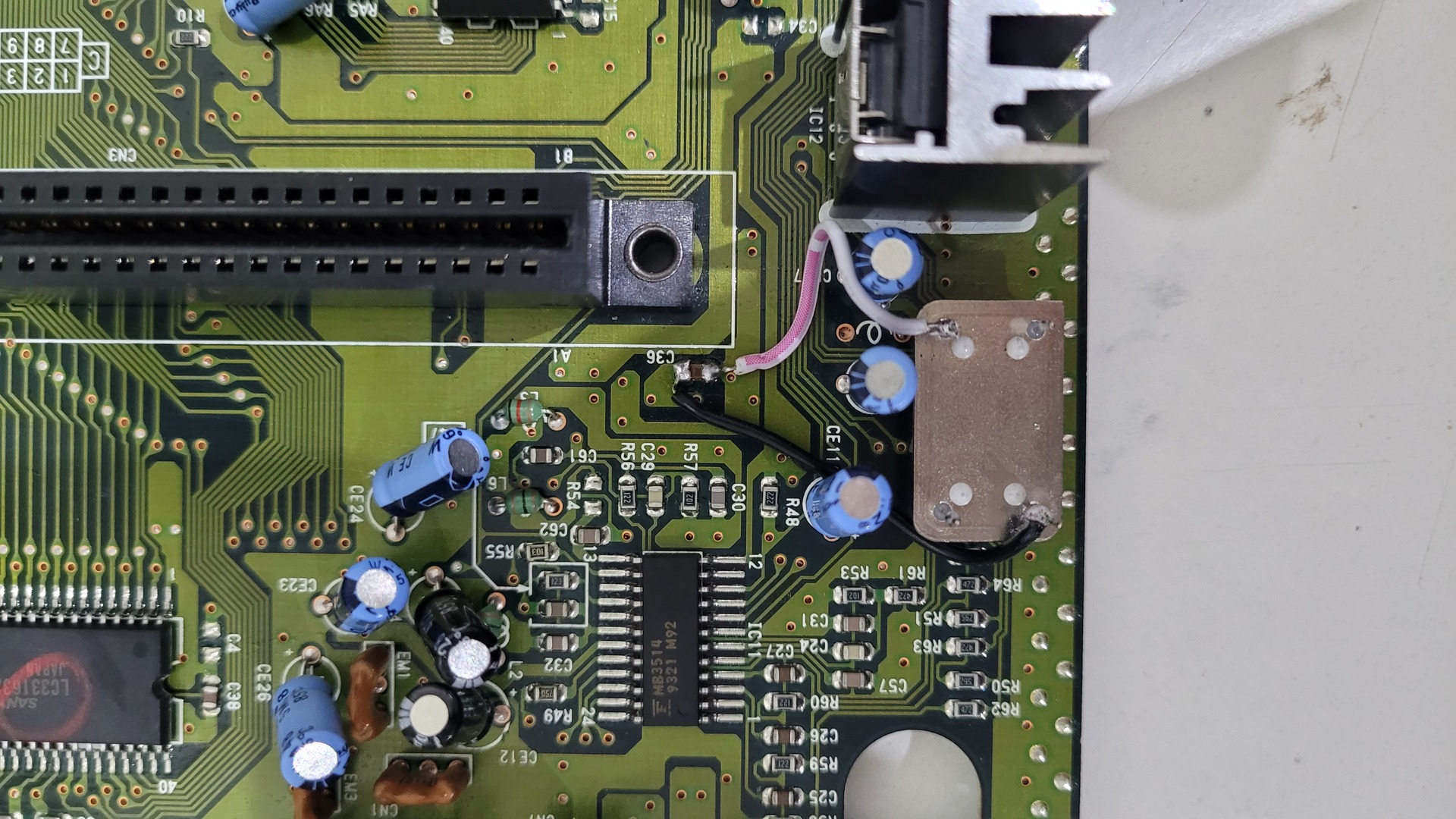
Clock hook
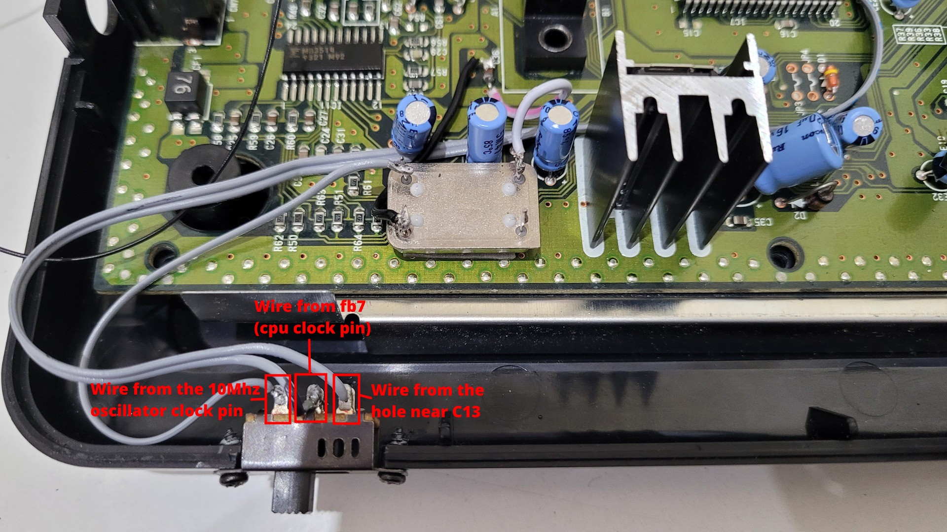
The 68000 CPU takes its clock signal from the pin 15. An option is to lift the pin to inject the required clock (7 or 10 Mhz). Another option, which is the one I chose, is to hook the signal in the area between c13 and fb7. I found this easier to do, but the trace must be cut (thus it’s destructive).
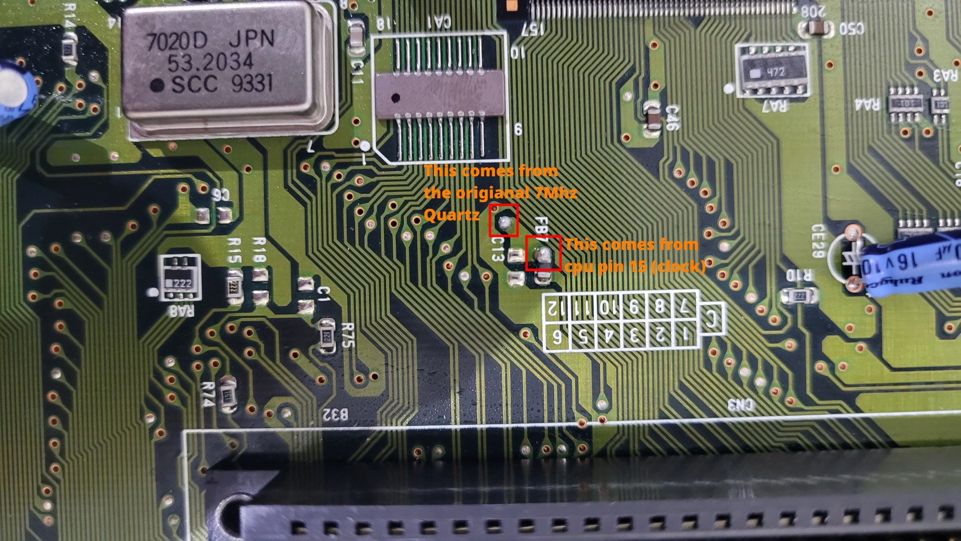
So basically, we need to solder two wires (one on both points) and cut the trace between the these points. The wire that comes from the CPU clock signal will later be soldered to the middle pin of the 3 pins switch, and the wire that comes from the original quartz oscillator will go to the first or third pin of the switch.
Below are the two wires soldered to the both points with the trace that have been cut.
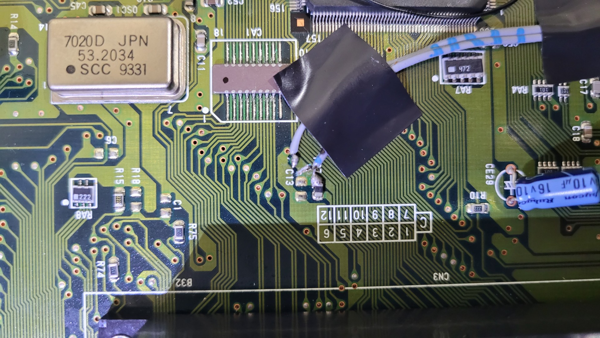
10MHZ quartz
I placed the new 10 Mhz oscillator upside down on the right part of the motherboard. I fixed it with some double sided tape.
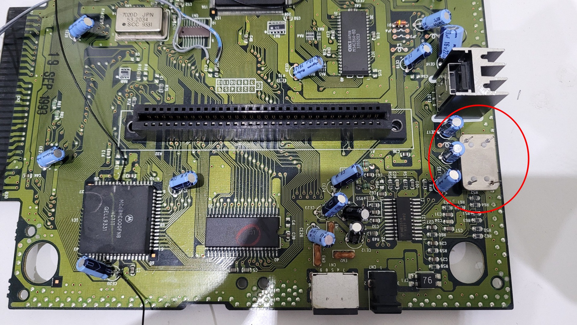
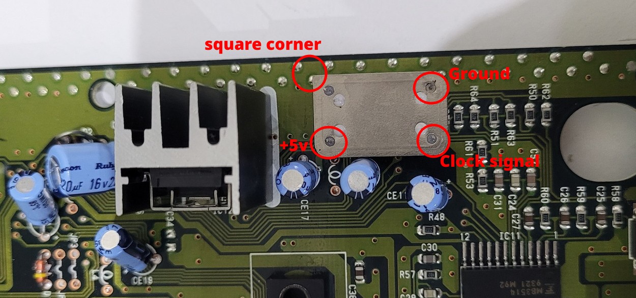
Only 3 pins are usefull : +5v, ground and clock signal:
Here is how I wired +5v and ground from C36. Black wire is ground, grey and red wire is +5v
I wired the clock signal later, after I fixed the switch.
Shell modding
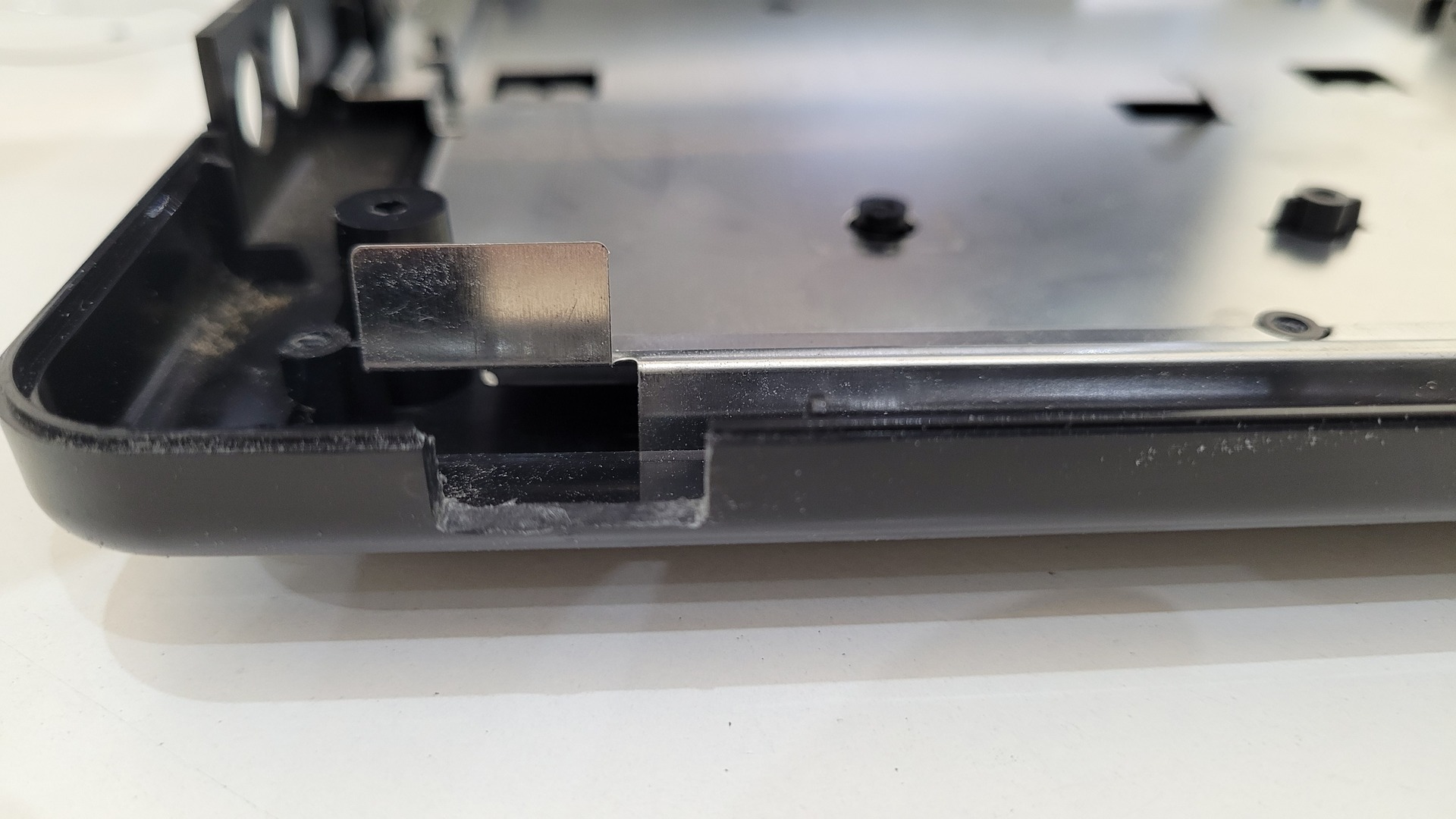
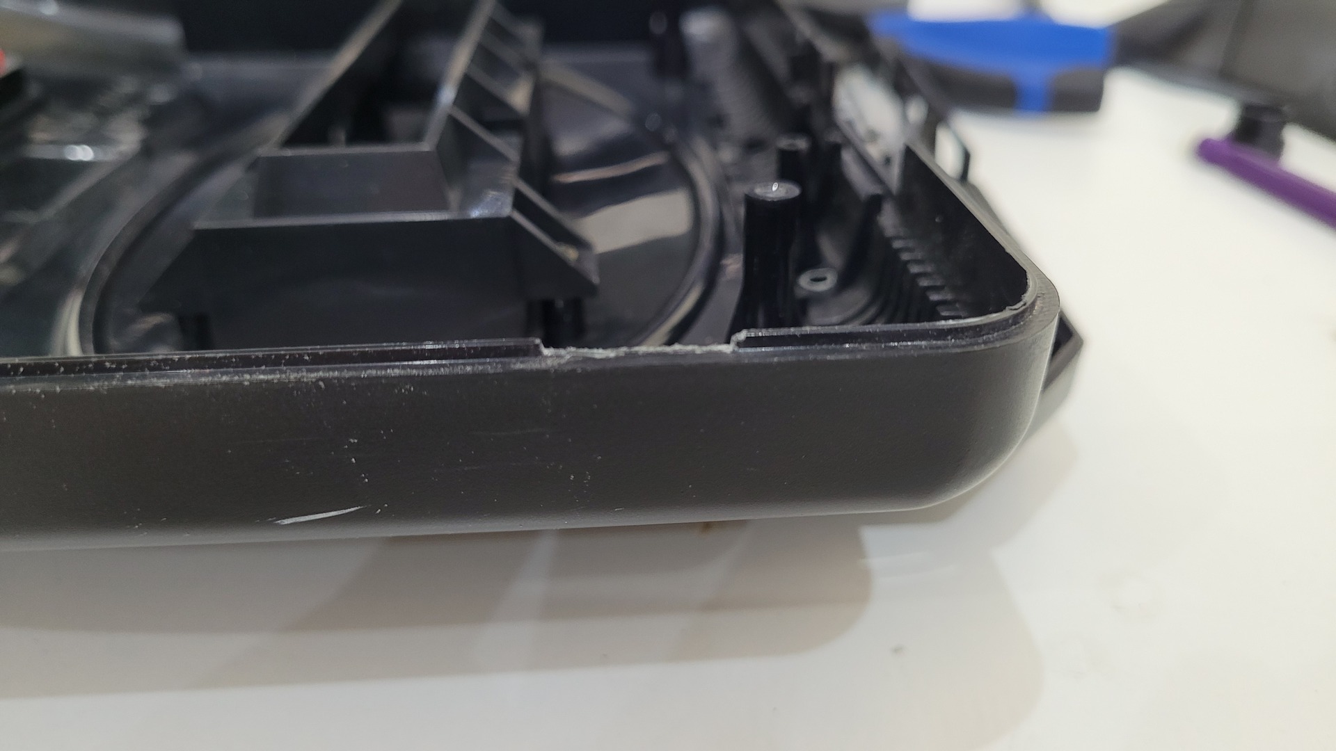
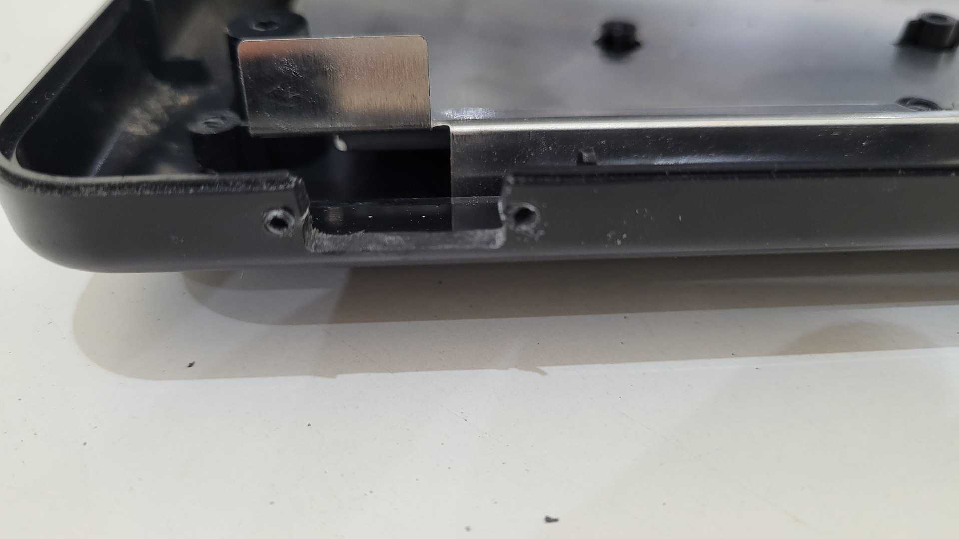
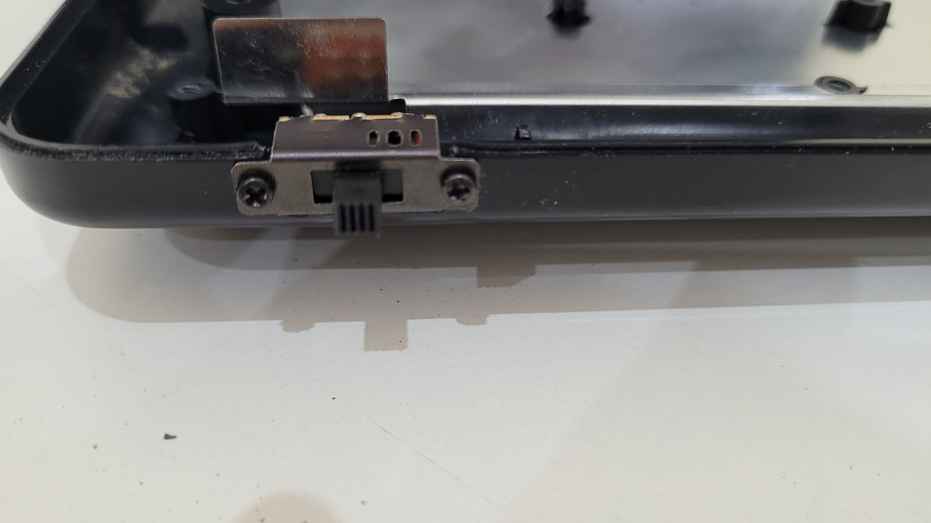
Frequency switch
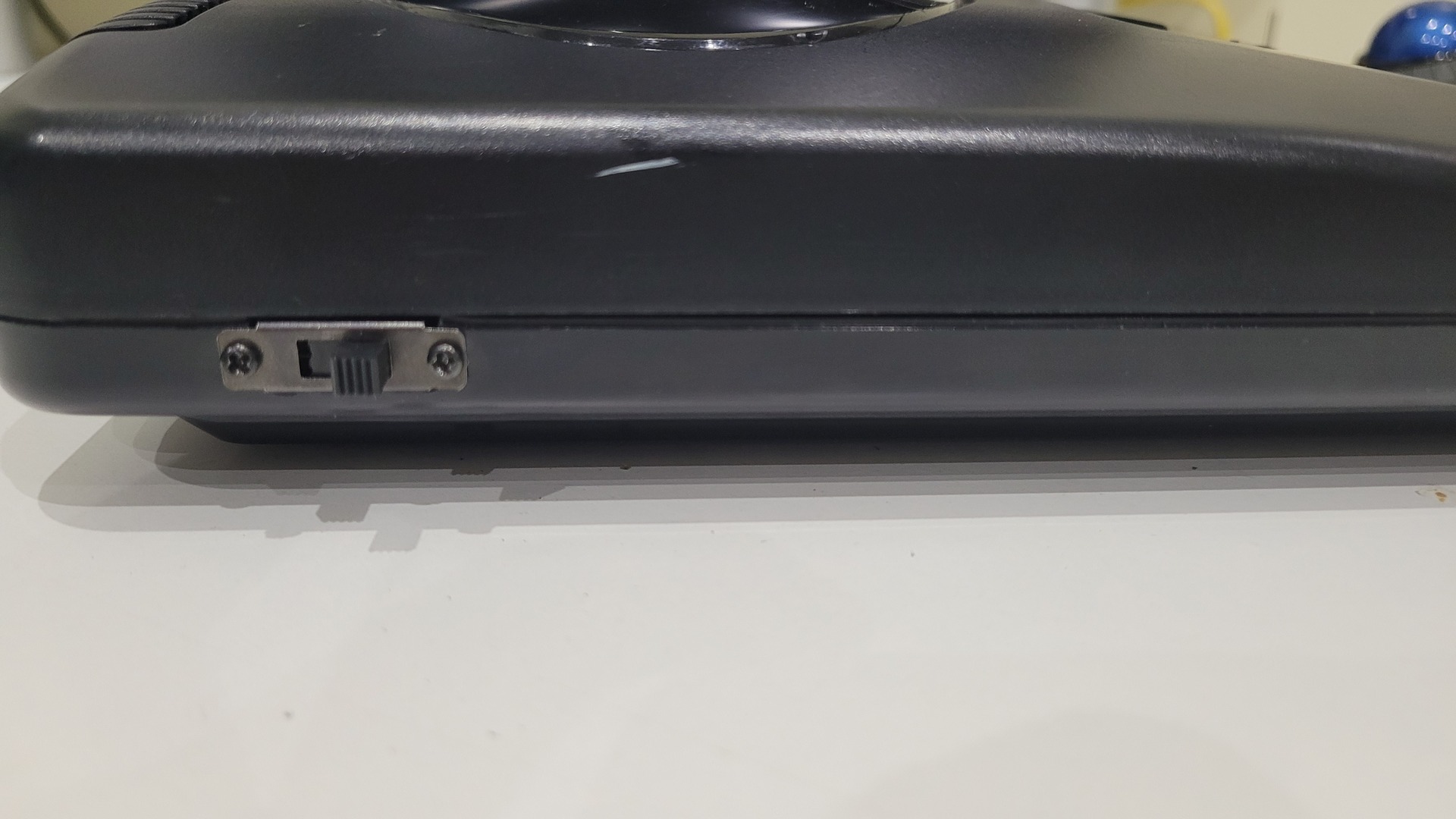
I placed the frequency switch on the left of the Megadrive, near the back corner. I made a square hole with a dremel in the bottom shell, and I removed a bit of plastic from the upper shell with a flat small. file. I also did two small holes to screw the switch. The wires are soldered later (see “frequency switch – part 2”)
CPU Alt switch
The CPU alt switch is optional. The purpose of this switch is to put the M68000 in “pause” so the frequency can be changed while the console is running, otherwise the console would crash. I used a momentary switch because I actualy found it more handy to use : I just maintain this switch pushed while changing the frequency.
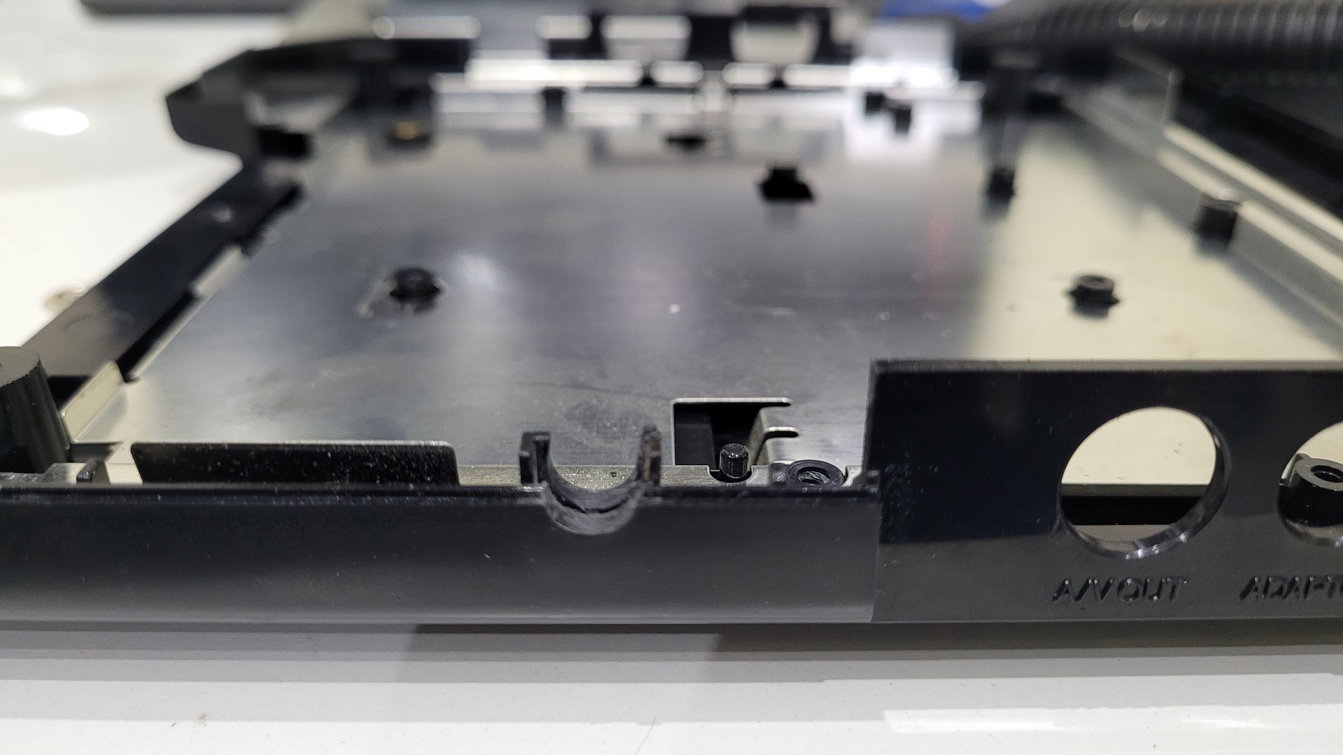
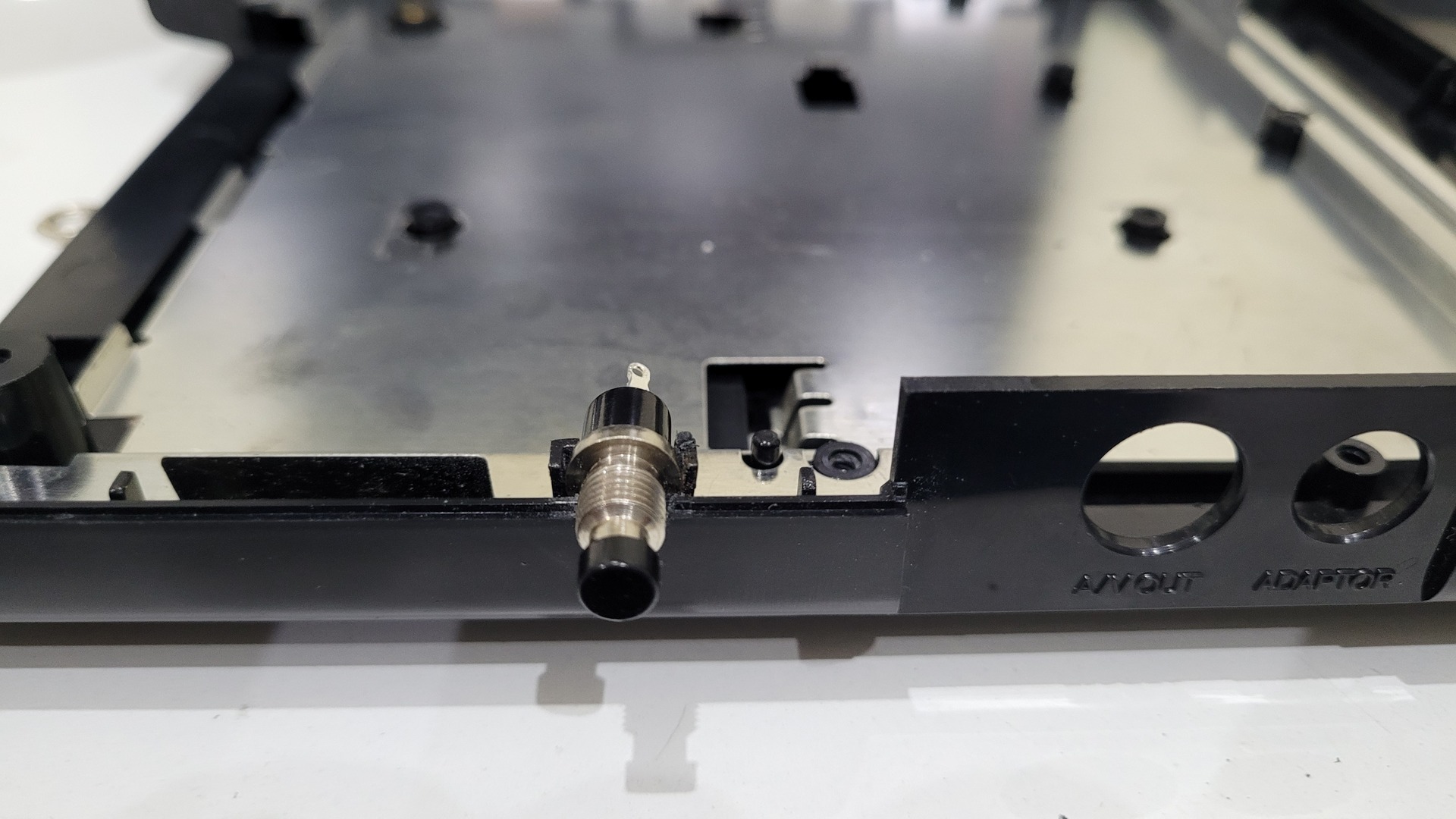
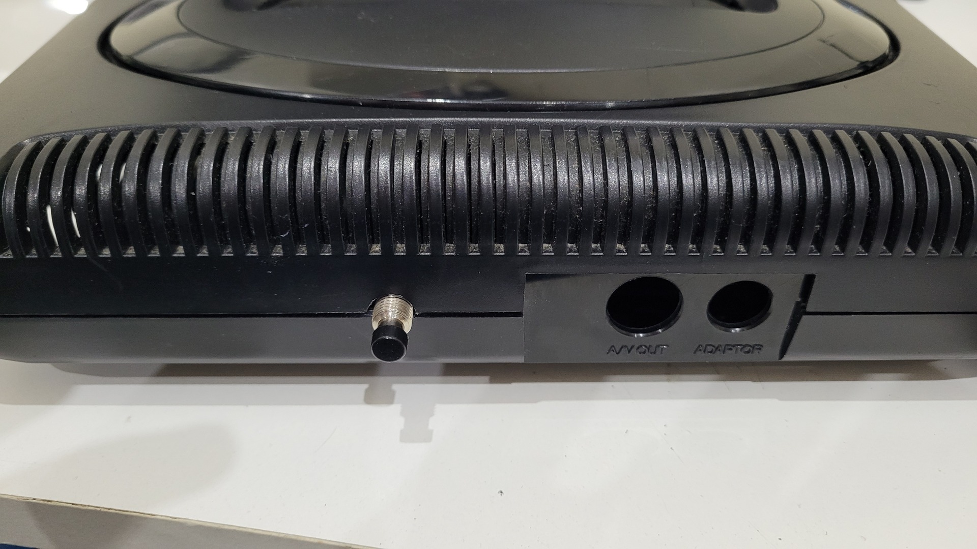
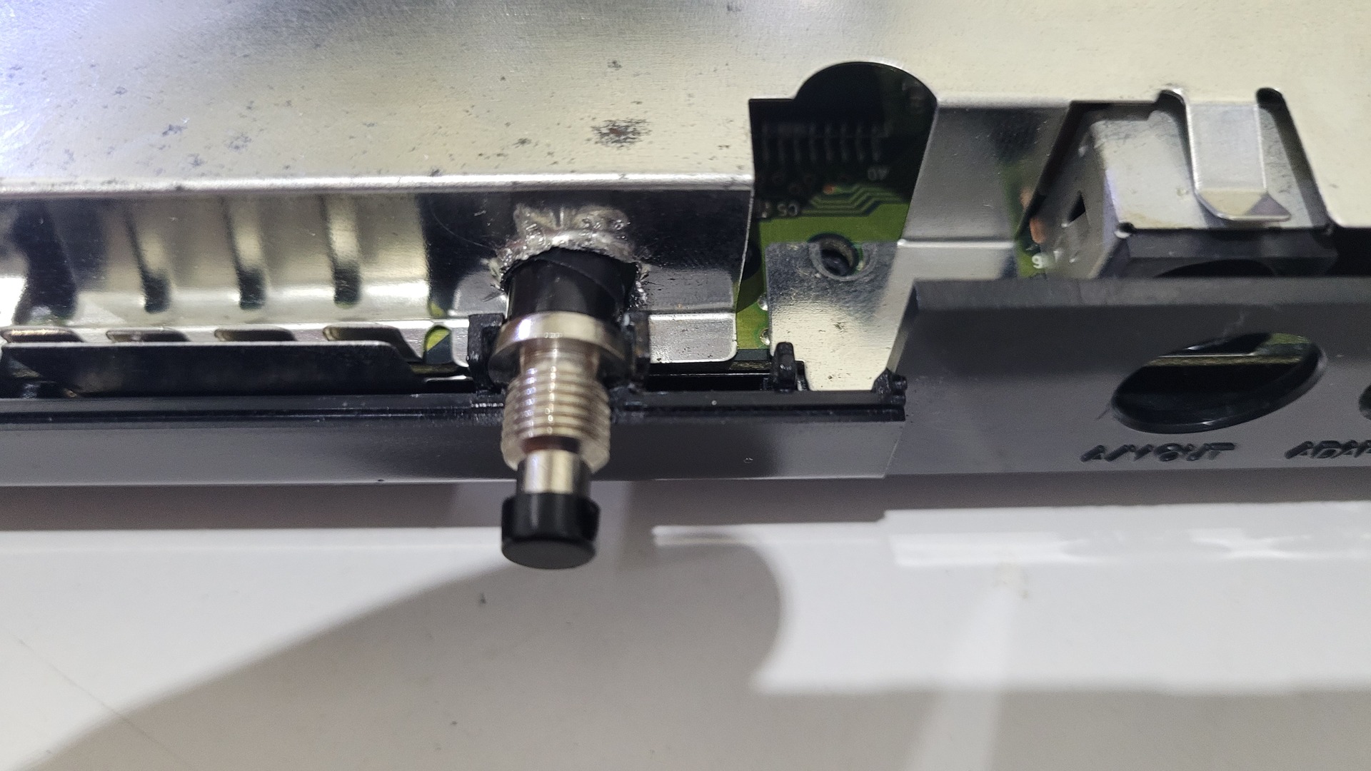
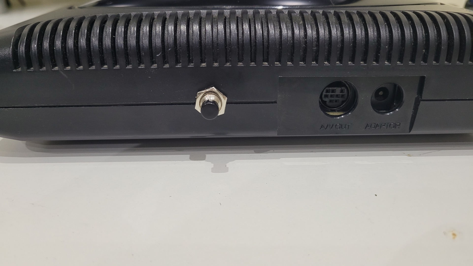
I used a small rounded black switch. On the Megadrive 2, there is already a round hole on the back of the console, next to video and power plugs. This hole just need to be a little bit widened with a dremel.
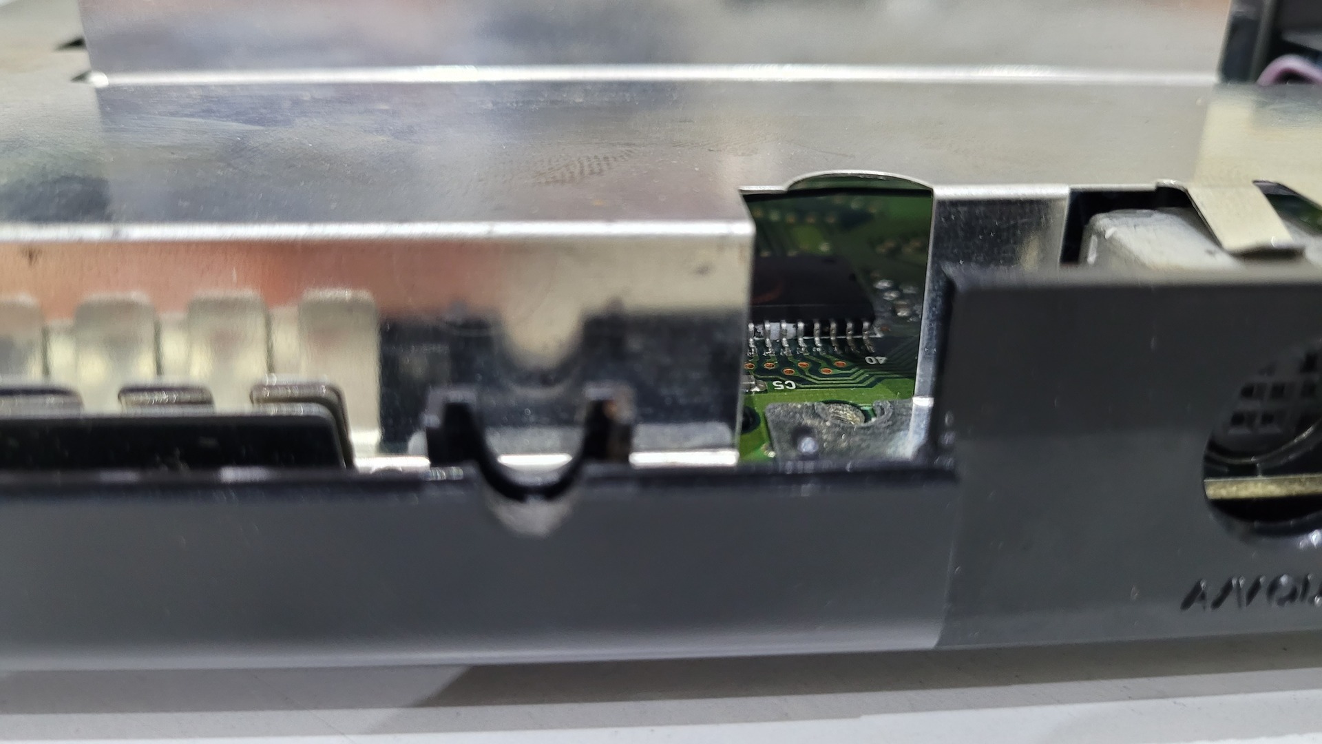
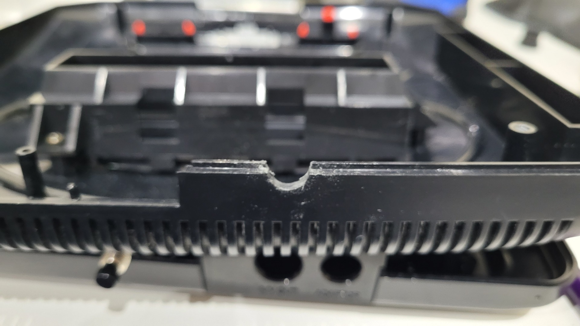
A quick check without motherboard and the metal shield to see if it closes correctly :
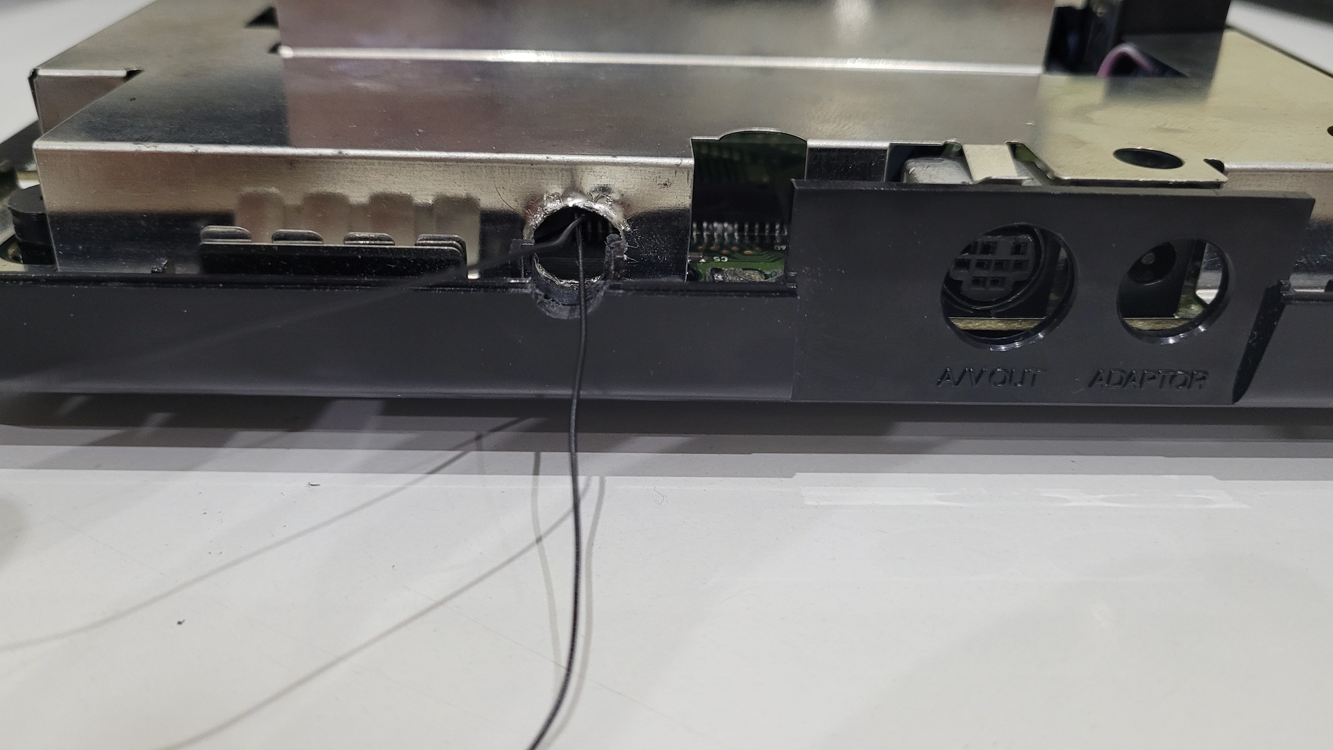
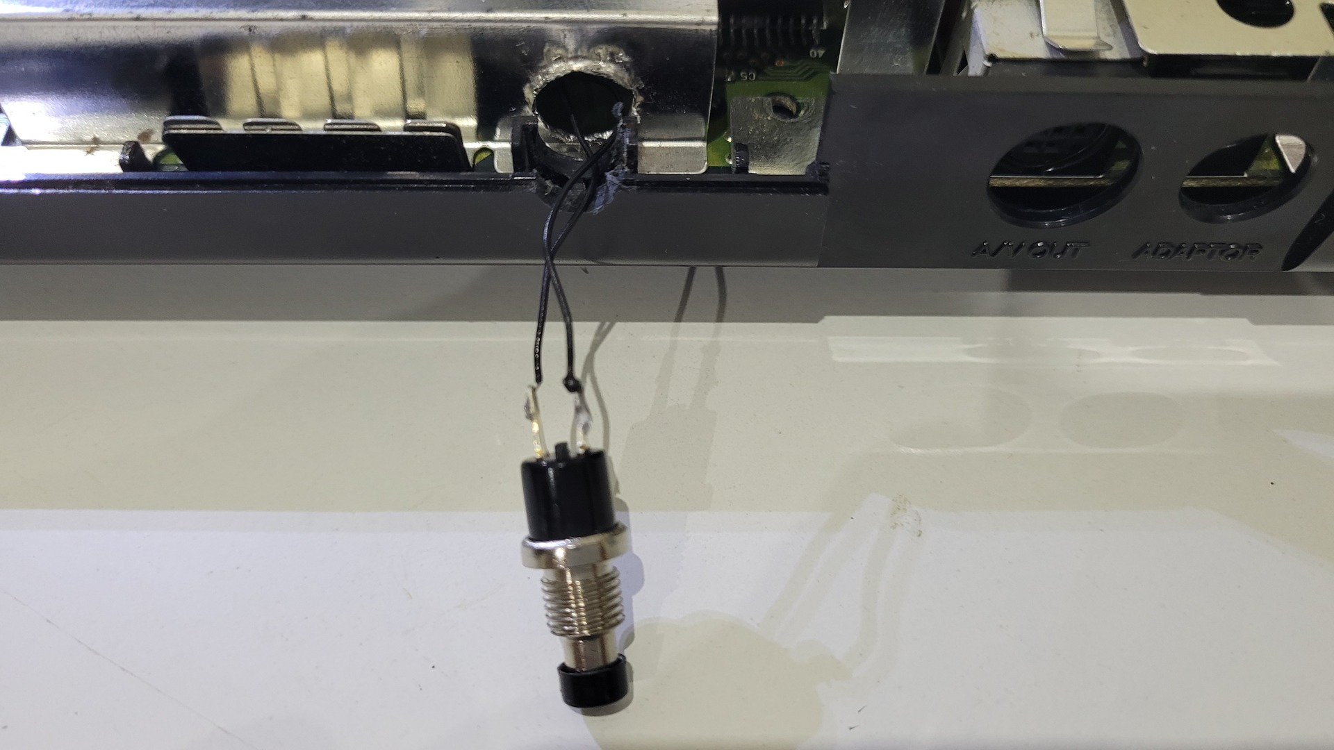
Next step is to pass the switch throught the metal shield before soldering wires. The shield must be drilled, unless you find a smaller switch. The wires to solder to this switch are just the one from CPU’s pin 19 and the wire from the ground.
Frequency switch – part 2
Before closing the console, the wires that come from both oscillators must be soldered to the 2 positions switch.
Final Result
7Mhz VS 10 Mhz in video
Other tests can be found on my dedicated playlist : https://www.youtube.com/playlist?list=PLyeuxrvAtEGrd4HG1Jx-hWpDHfd841M55

interesting. Could this damage the 68k in the medium or long term?
I’m not expert, but I doubt this kind of overclocking could damage the CPU. At least, Temperature wise, my overclocked 68k does not go over 38/39°C, whereas it is rated for 70°C if I’m not wrong