The Sega Megadrive for PAL regions, like other consoles from the 90′, suffered from slow games because of 50hz TV, thus 50 fps max versus 60Hz, thus 60 fps max in NTSC regions. Some later games had been “optimized” for 50HZ and in this case, you must take the japanese or US version to play in 60 fps (e.g : Sonic 3, Street of rage 2 and 3). However, a lot of games work out of the box in 60Hz even if they have been tagged “PAL”. This is the purpose of the switchless mod : changeing the region code and the TV output standard of a PAL console. If you are used to solder, this mod is simple, cheap (around 10 euros), and it’s a real game changer for the PAL Megadrive, allowing to play all US and Japanenes games as well as most PAL games in 60Hz.
Here is the story of my modded PAL Megadrive…
Used Materials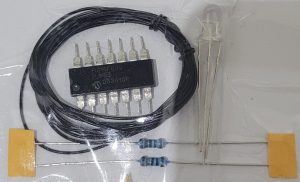
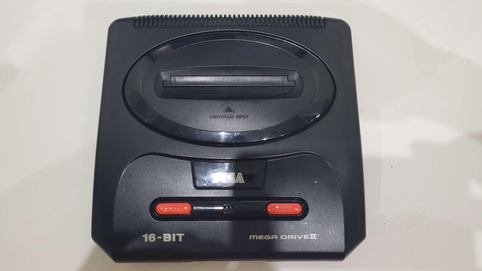
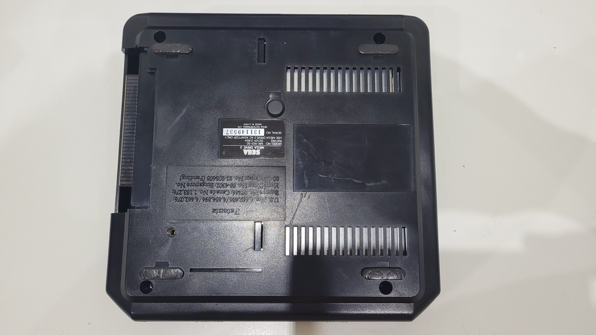
- Obviously, a PAL Sega Megadrive, mine was a VA1 model. It’s the same as VA0. Other models are a little bit different.
- A Switchless kit. It can be found on ebay (I got mine from a seller named “drogba94”)
- A knife or a cutter to be able to scratch some traces
- A solder Iron with a fine tip and some tin wire
Step by step mod
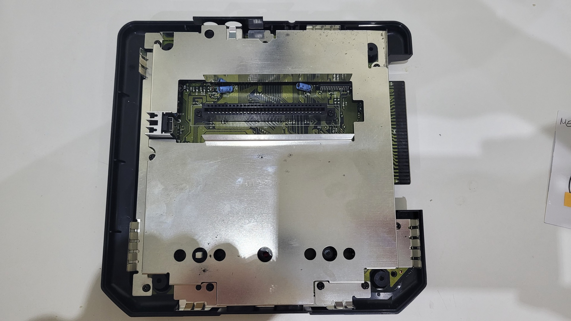
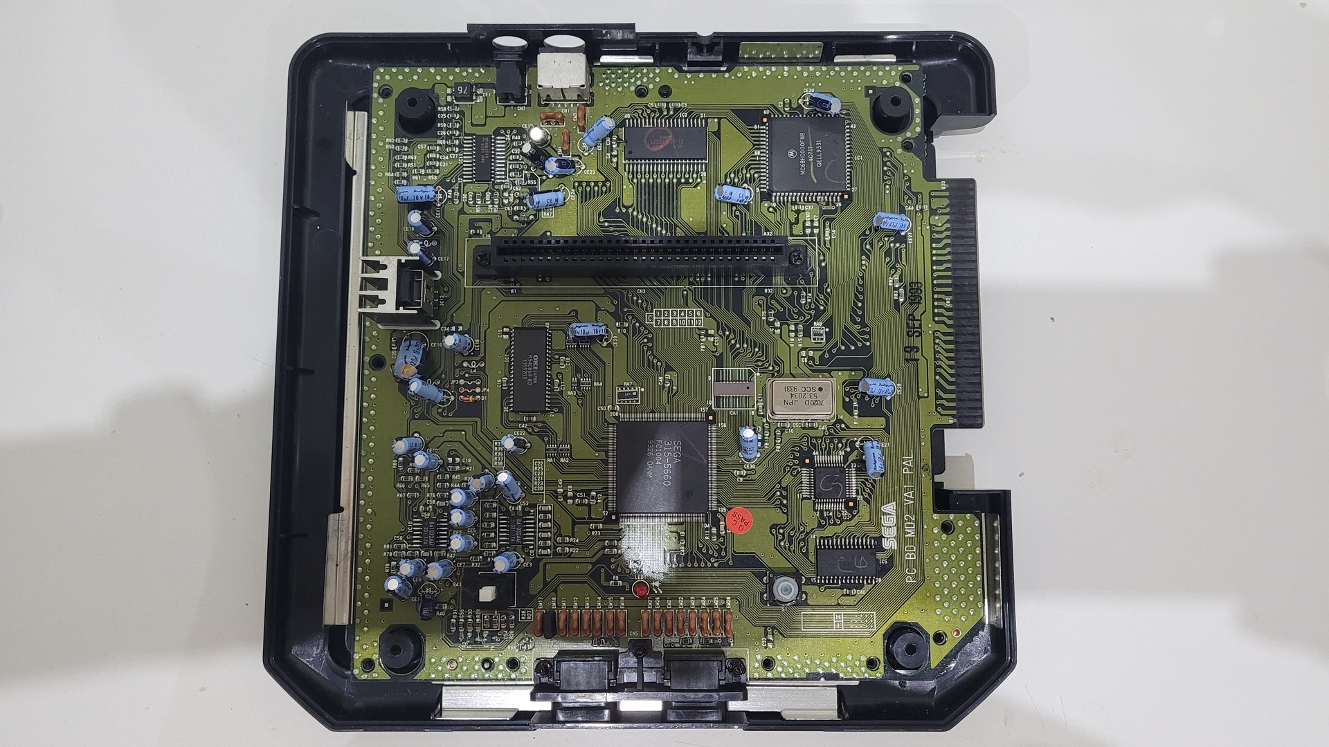
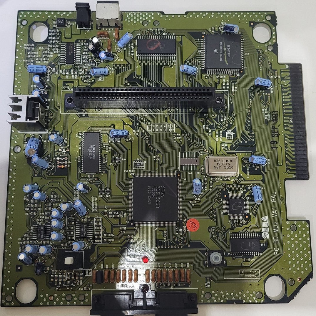
Remove the Motherboard
Extracting the motherboard consists in opening the plastic shell, removing the metal shield and removing all screws from the motherboards.
Prepare the 3 traces to solder wires on it
This mod requires to solder 3 wires directly onto some circuit traces. I started by this step because it is easy to do while it is not destructive for the motherboard.
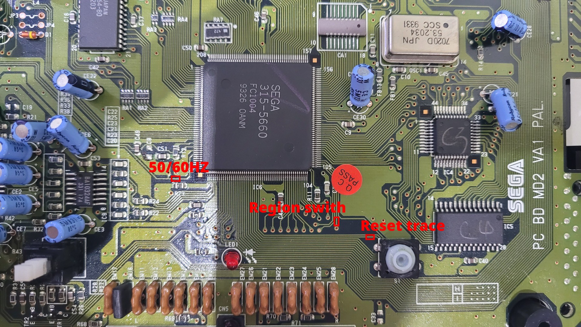
| 50 / 60 Hz | Reset Trace | Region switch |
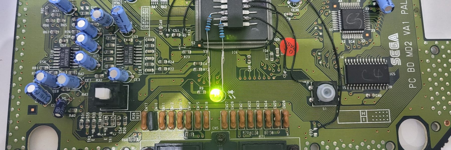
Solder wires to the motherboard
Now that traces are ready, we can solder all 6 wires to the motherboard. Each wire will be soldered to the PIC16F630 later.
To solder on a scratched trace, I just heated them up a bit before putting some solder, then I soldered the tined wire on it. On other solder points , I just added a little bit of solder before soldering the wire.
| Reset trace | Region Switch | 50 / 60 Hz |
| Ground | Vdd 5v | Reset signal |
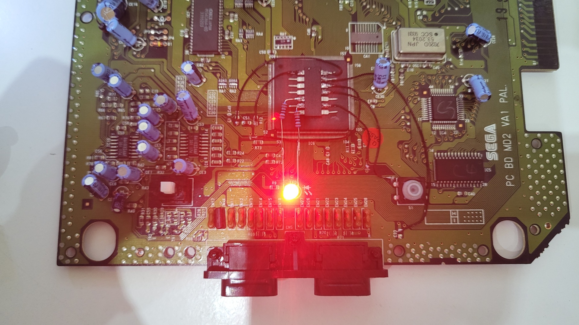
Replace the power LED
The orignal Power LED can be removed with ease by using a solder pump on the back of the mother board. Then, the middle leg of the provided dual color led must be soldered on the left pad of te original LED (ground).
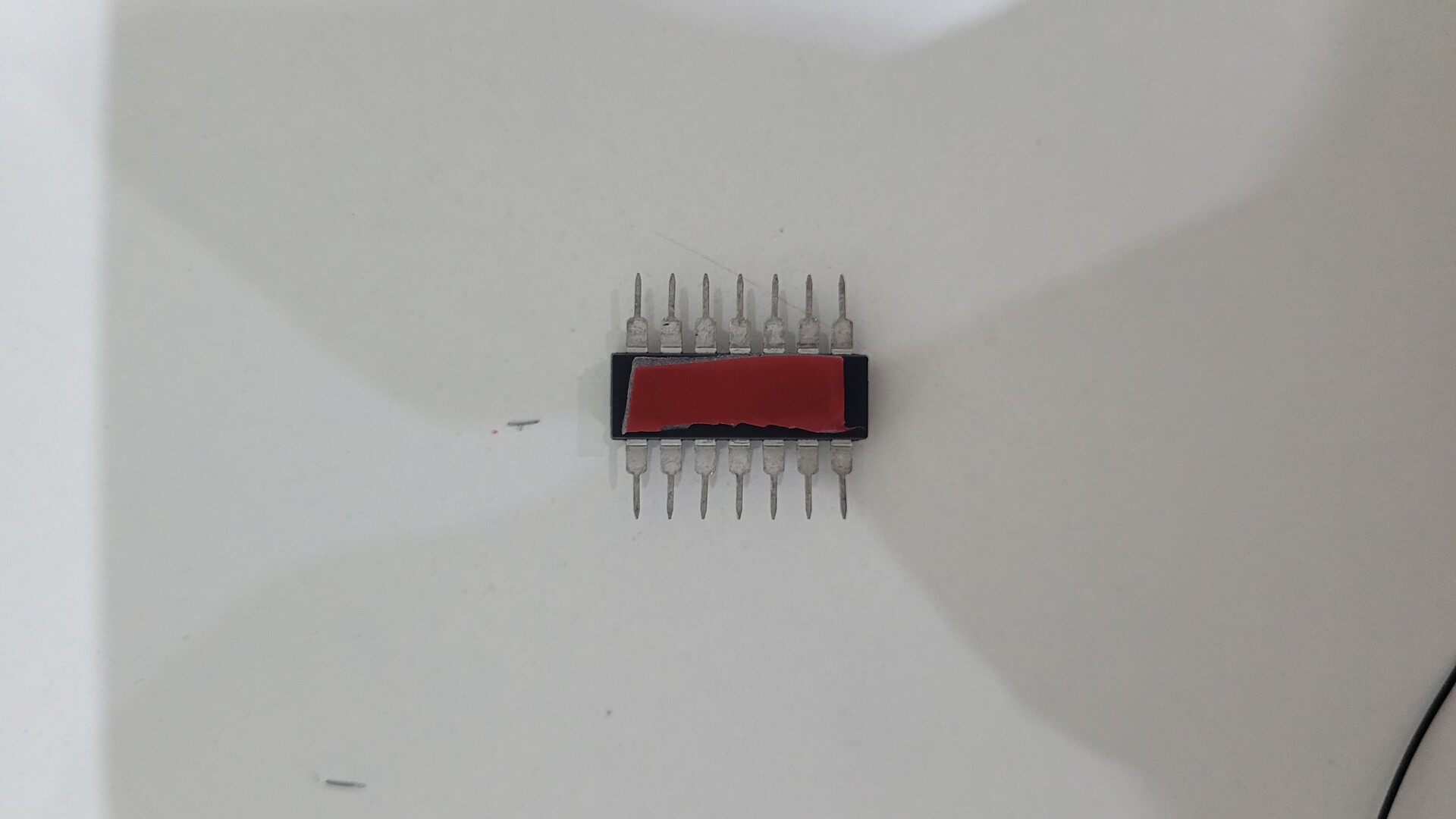
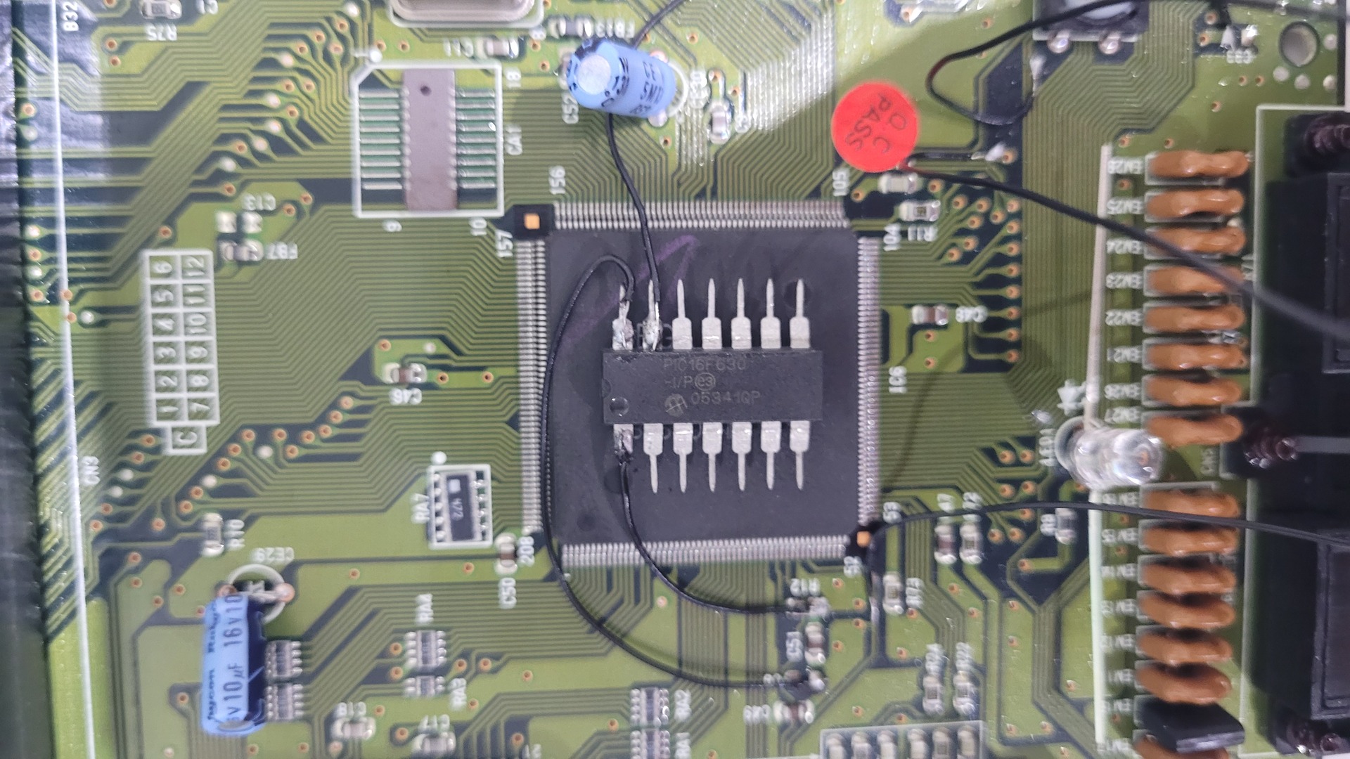
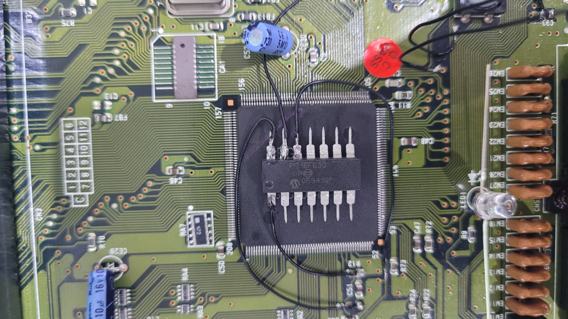
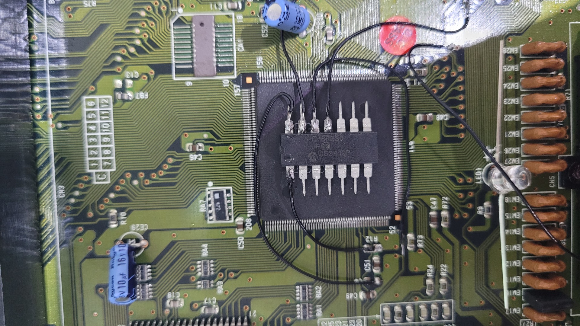
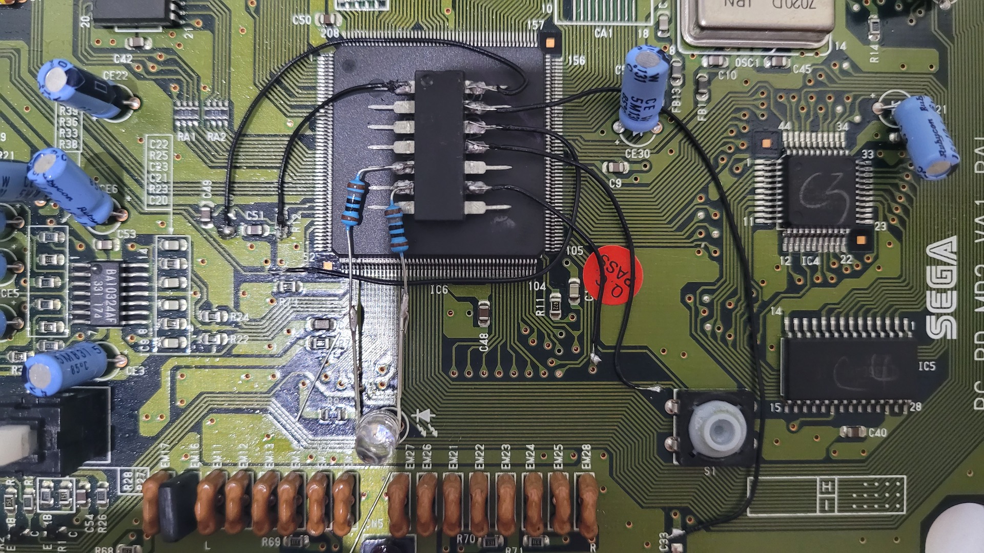
Solder wires to the PIC
The PIC can be fixed to the Sega 315-5660 chip by using some double face tape :
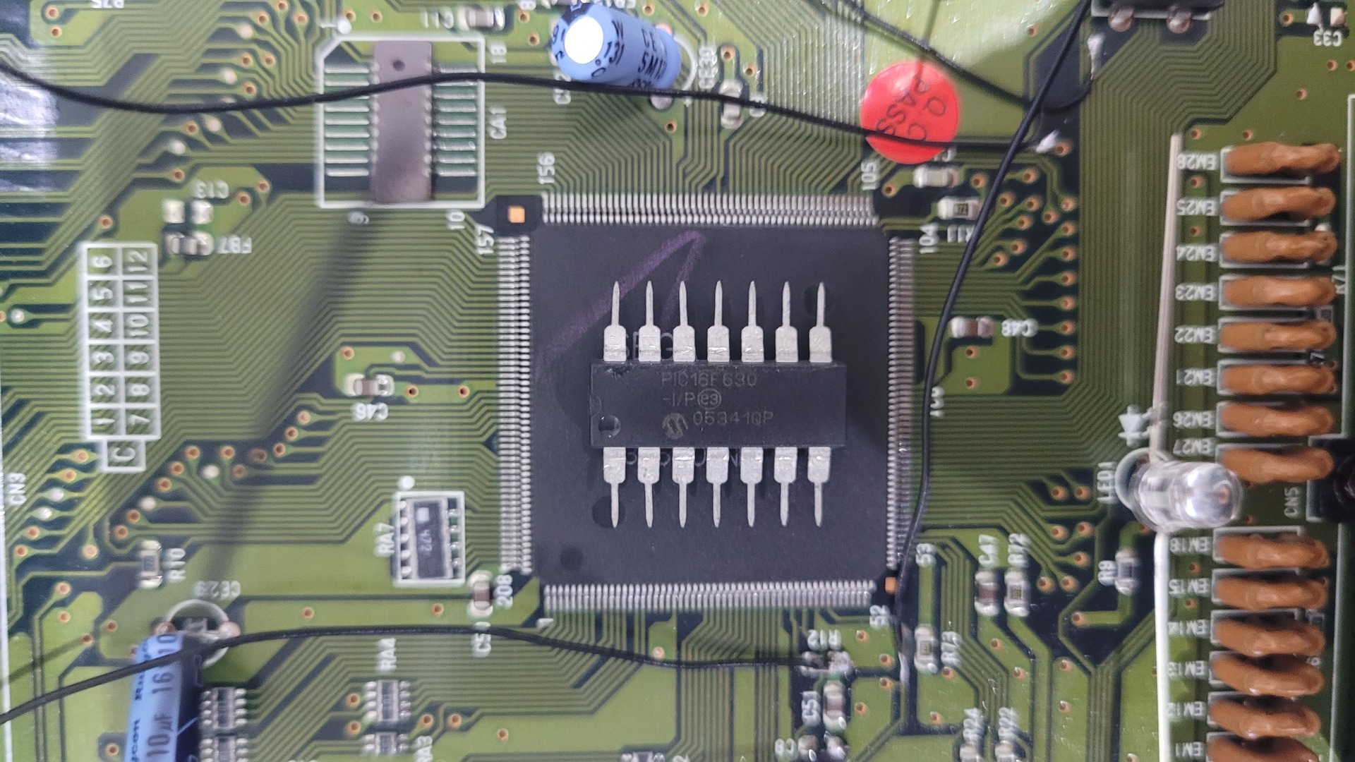
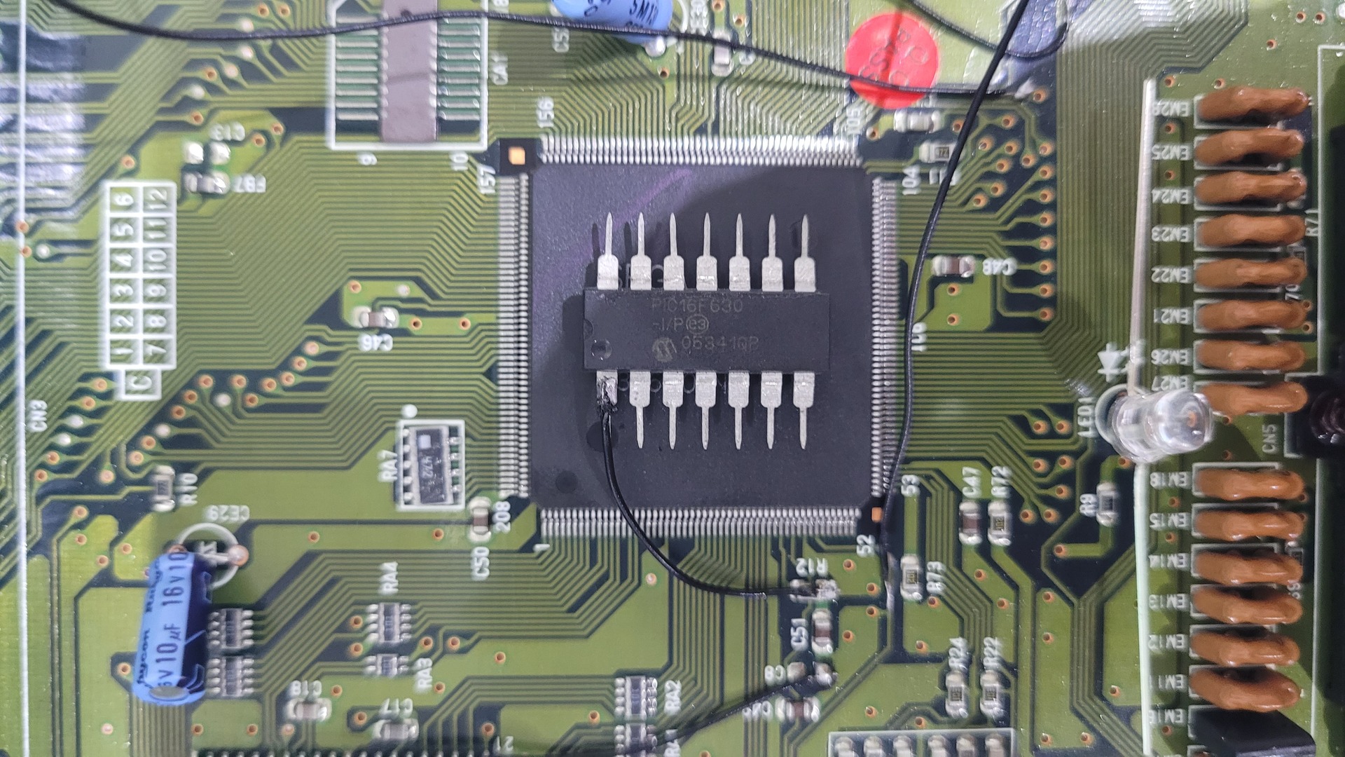
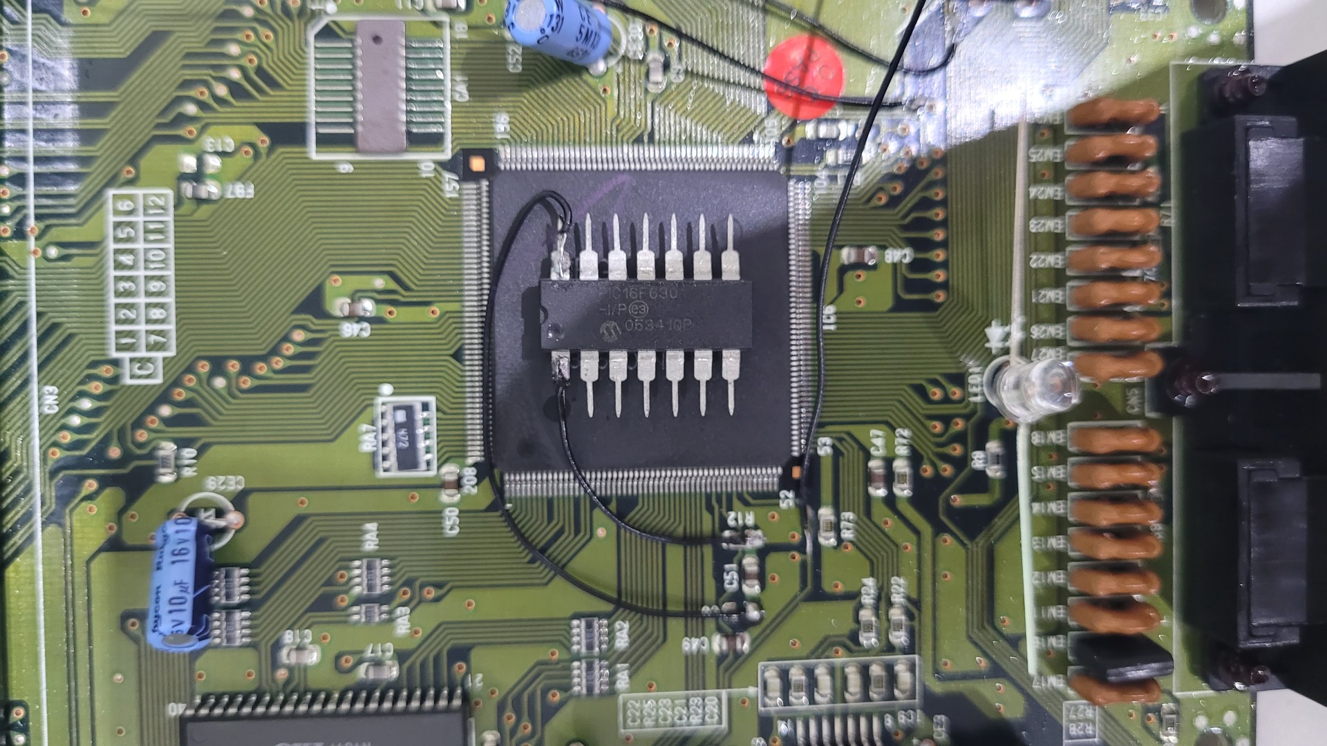
Now, that the motherboard is prepared, it’s time to take all wires one by one and solder them to the PIC :
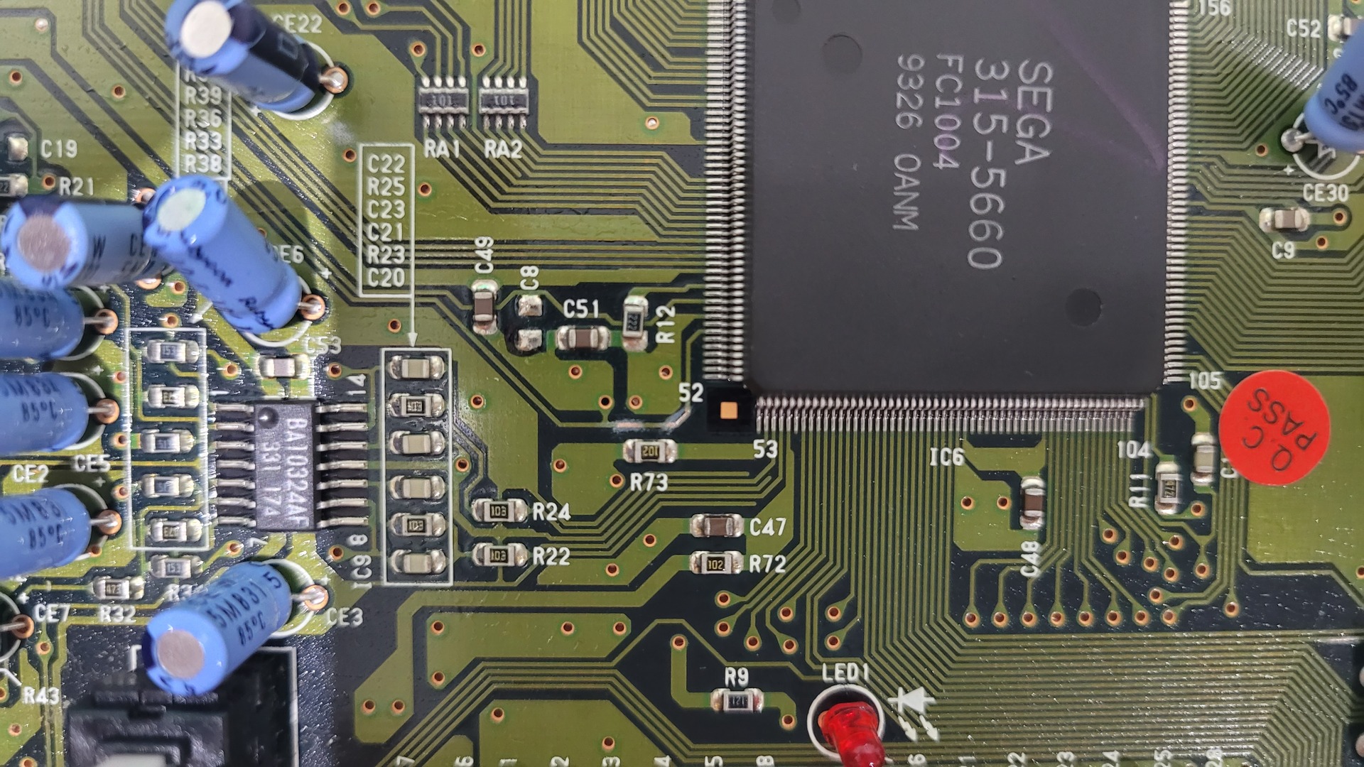
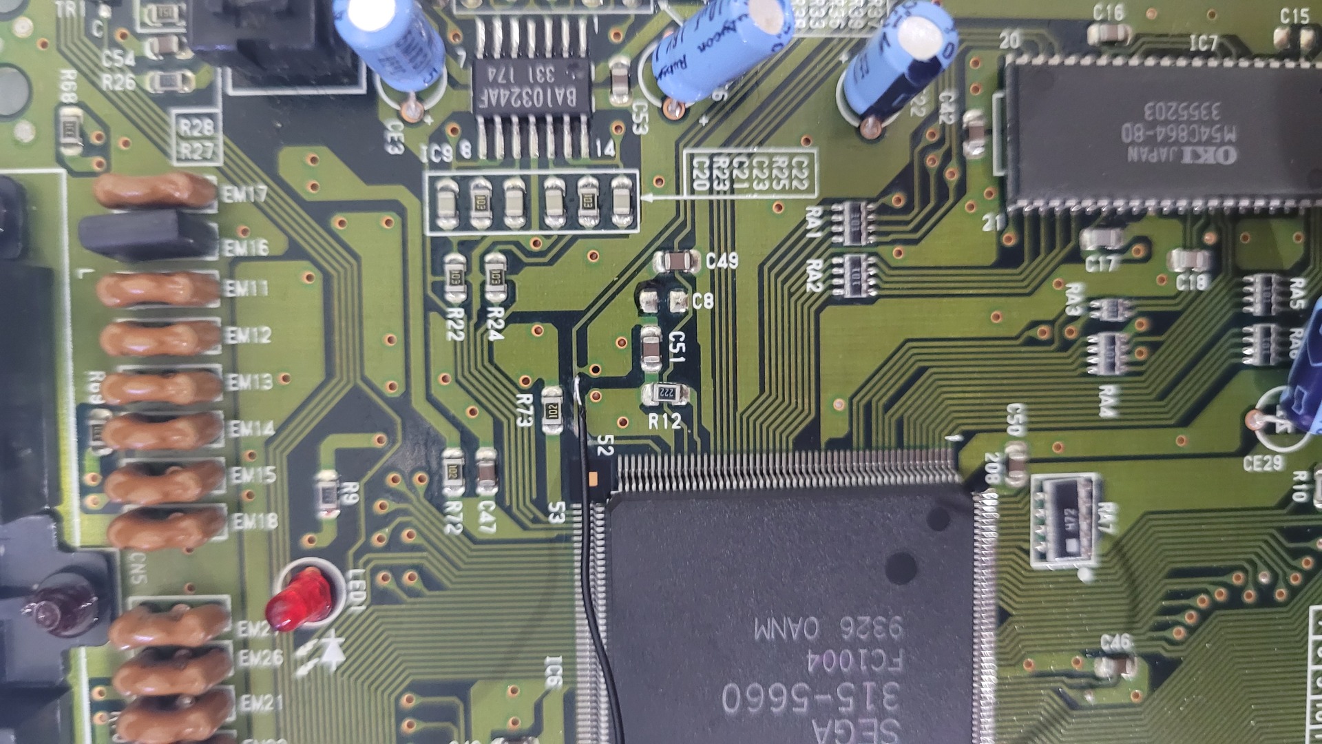
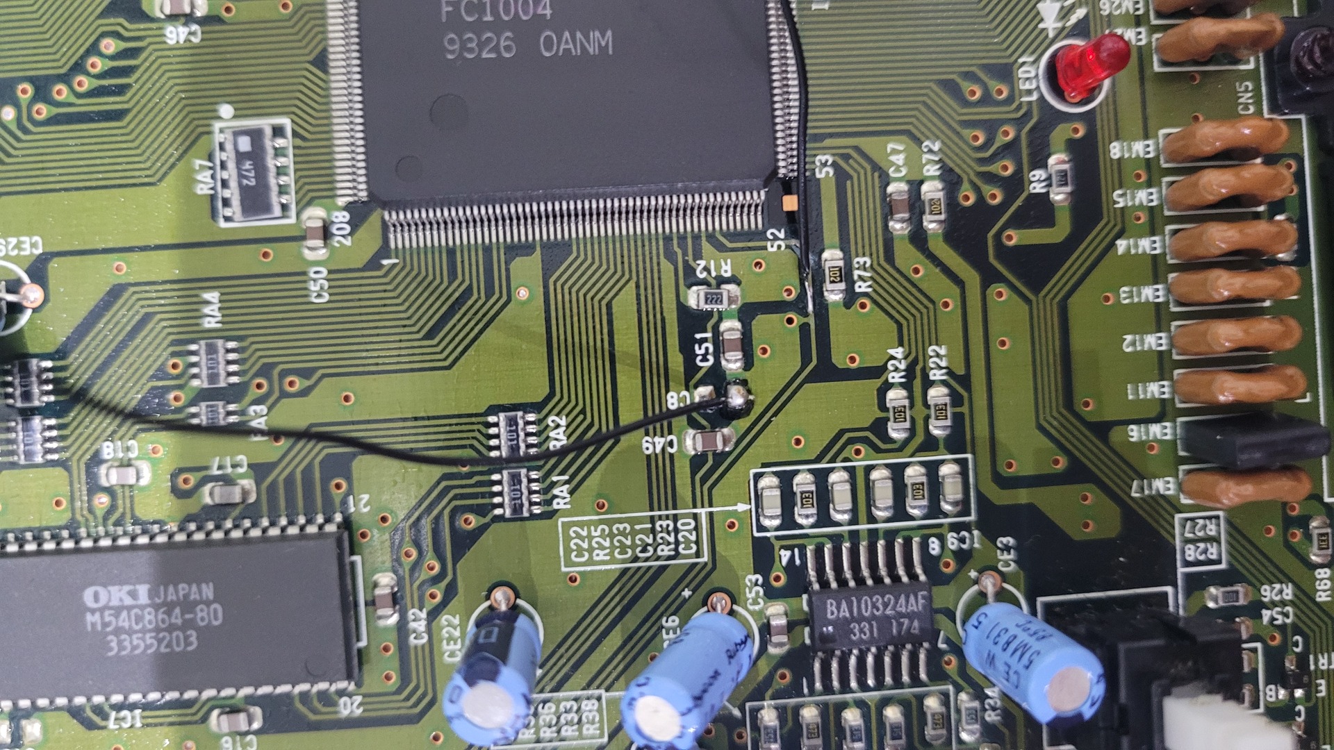
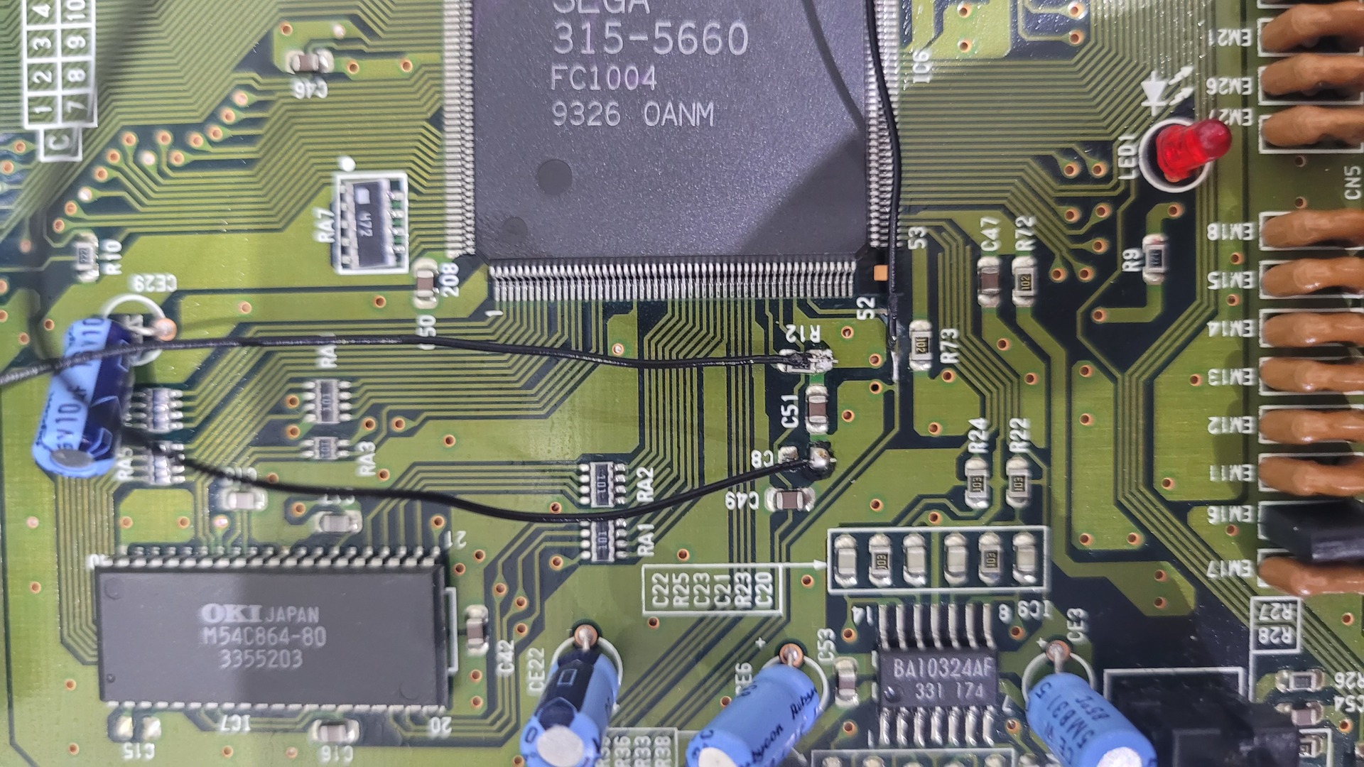
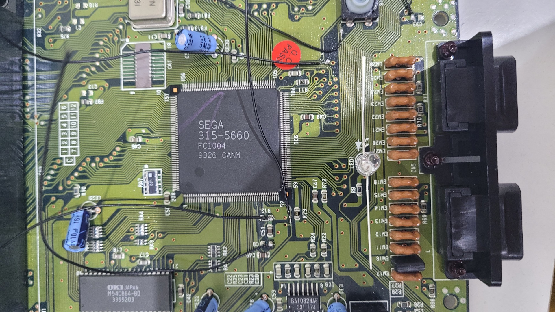
- Pin 1 : Vdd, 5v from the R12 positive (bottom)
- Pin 5 : One of the two led’s cathodes (don’t forget to put the provided resistors)
- Pin 6 : Other led’s cathode (again, put a resistor)
- Pin 14 : Ground from the C8 bottom solder point, to the left of C51
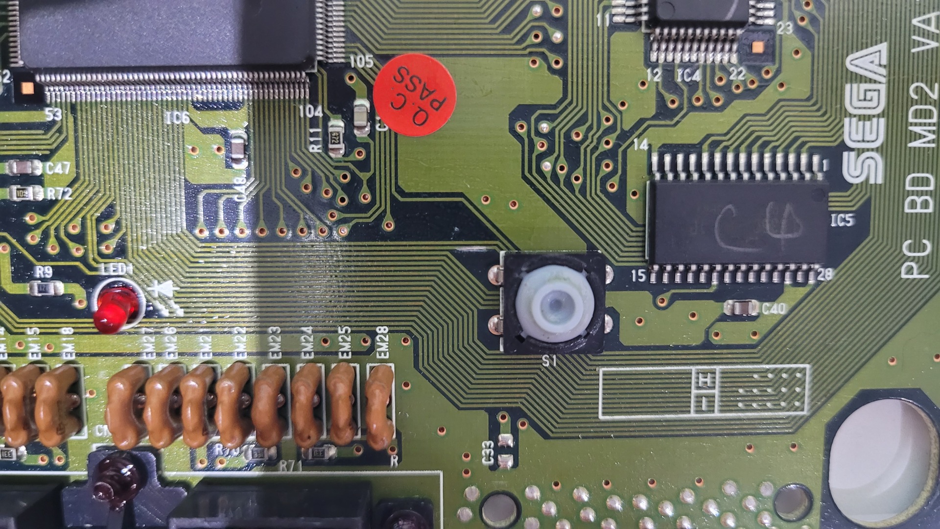
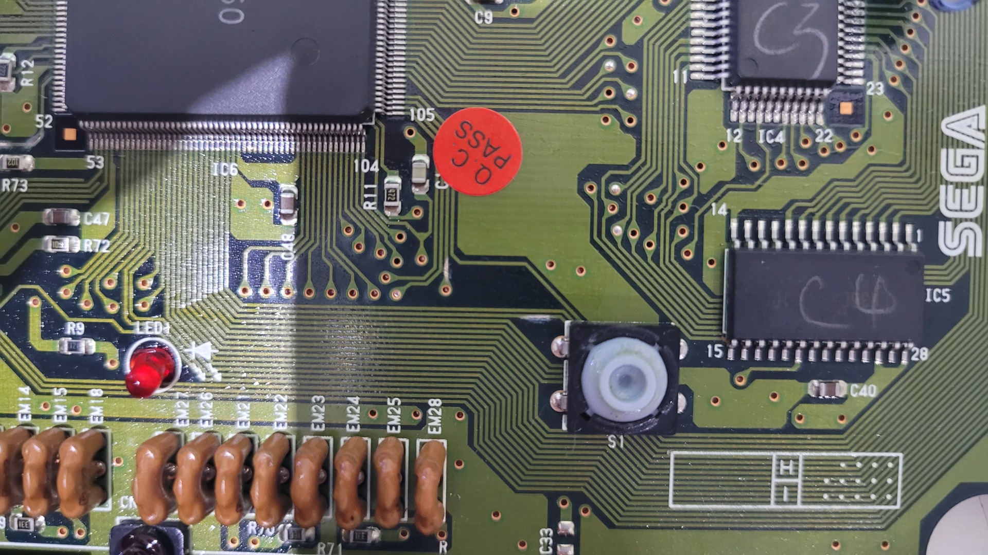
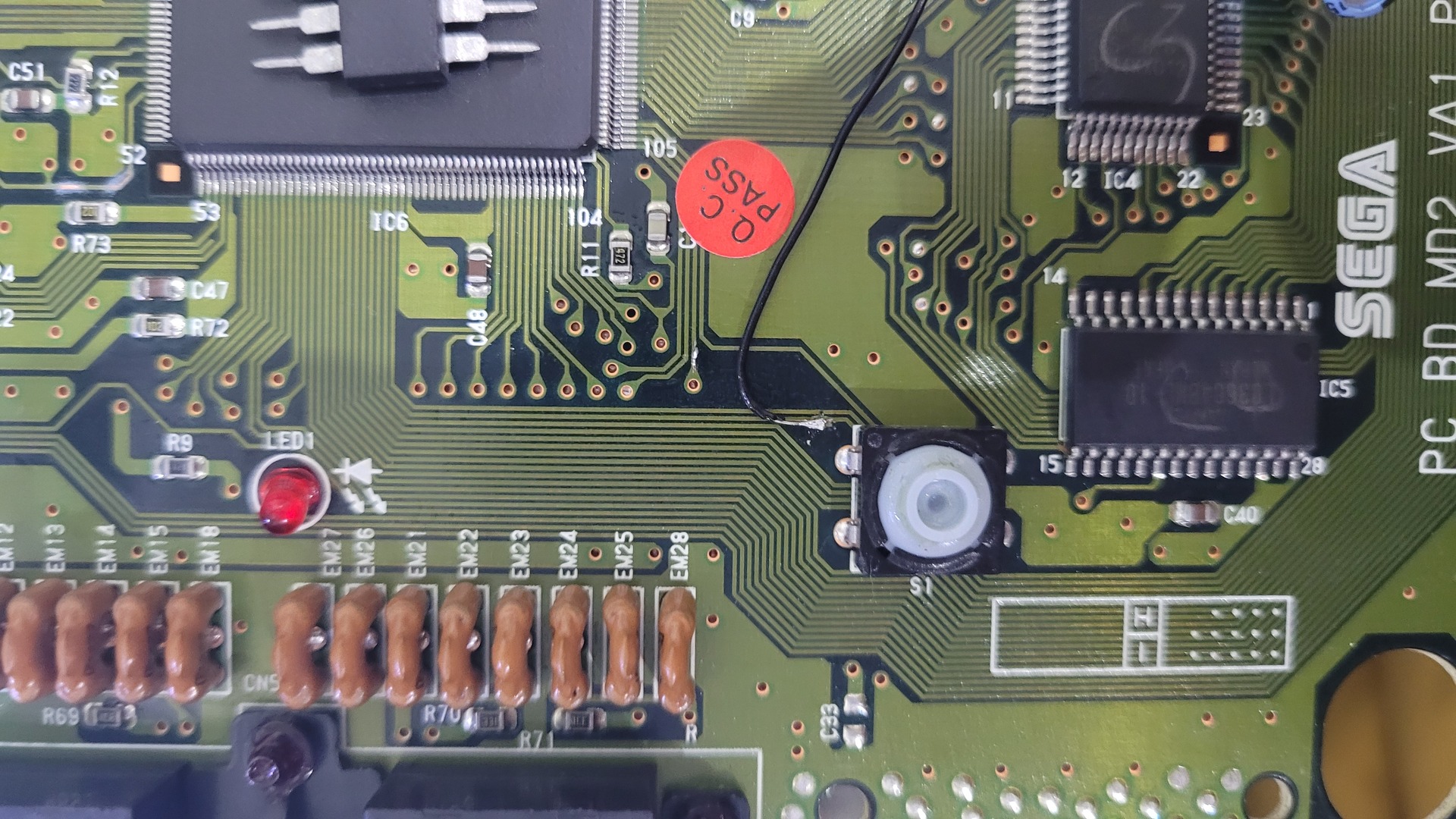
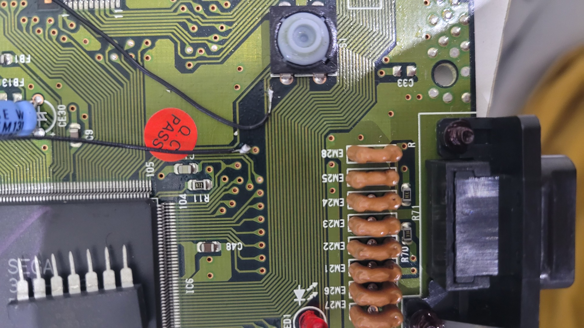
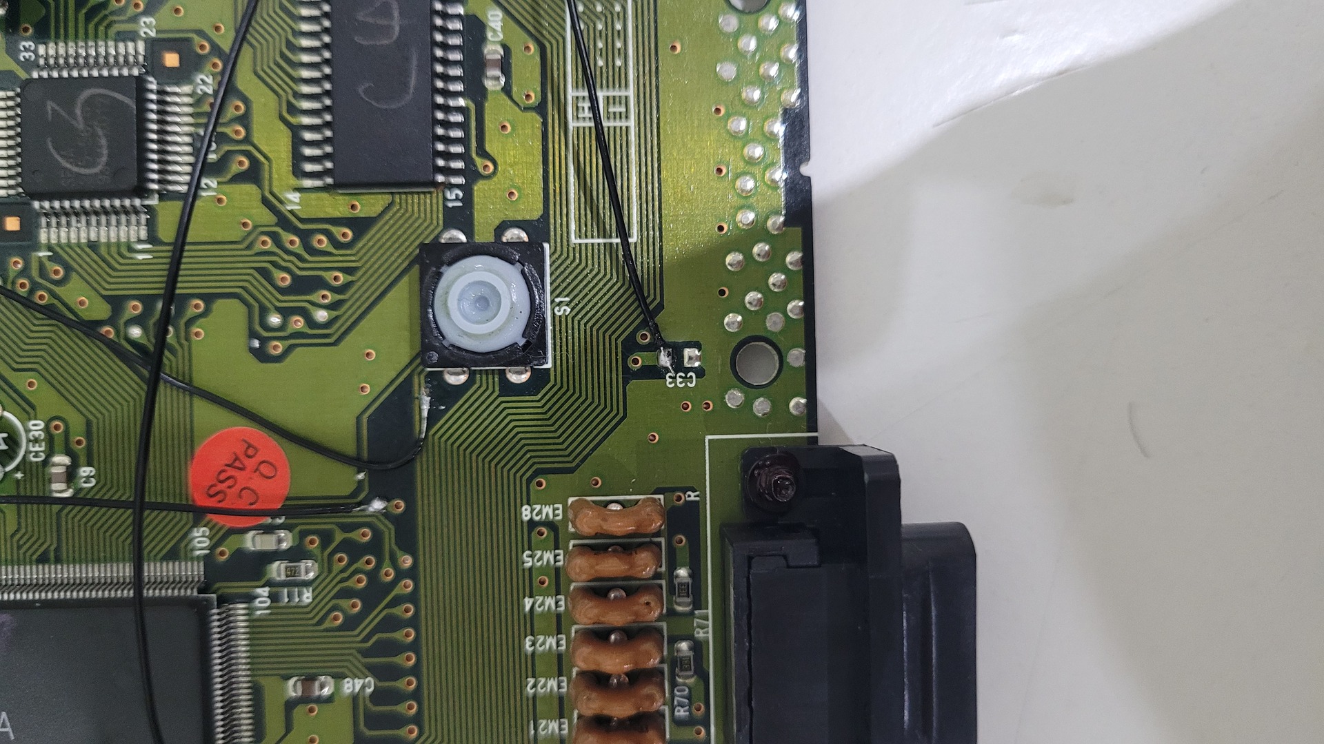
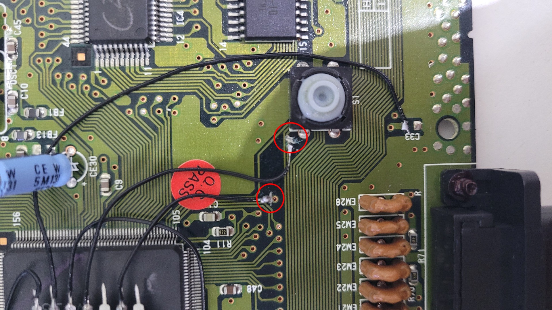
- Pin 13 : Reset button input, taken from the solder point just above C33
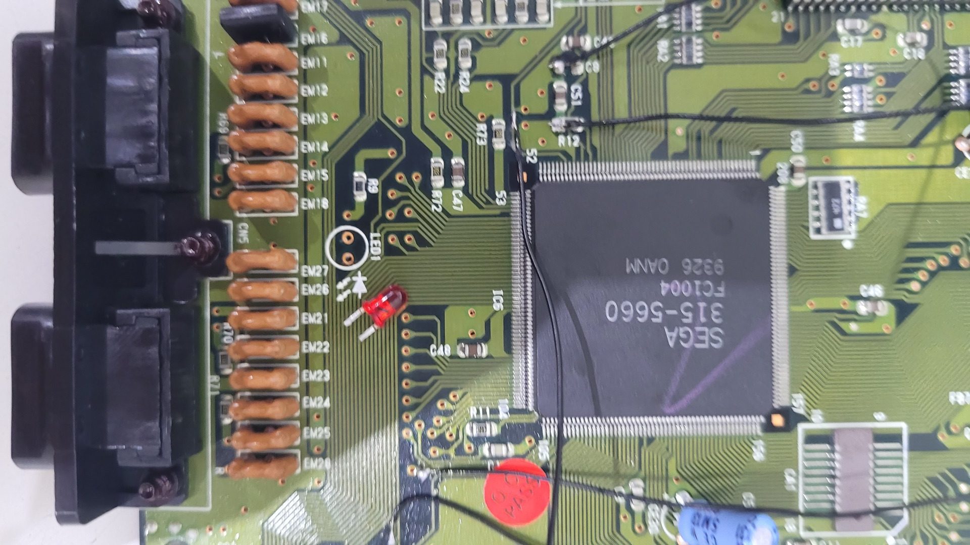
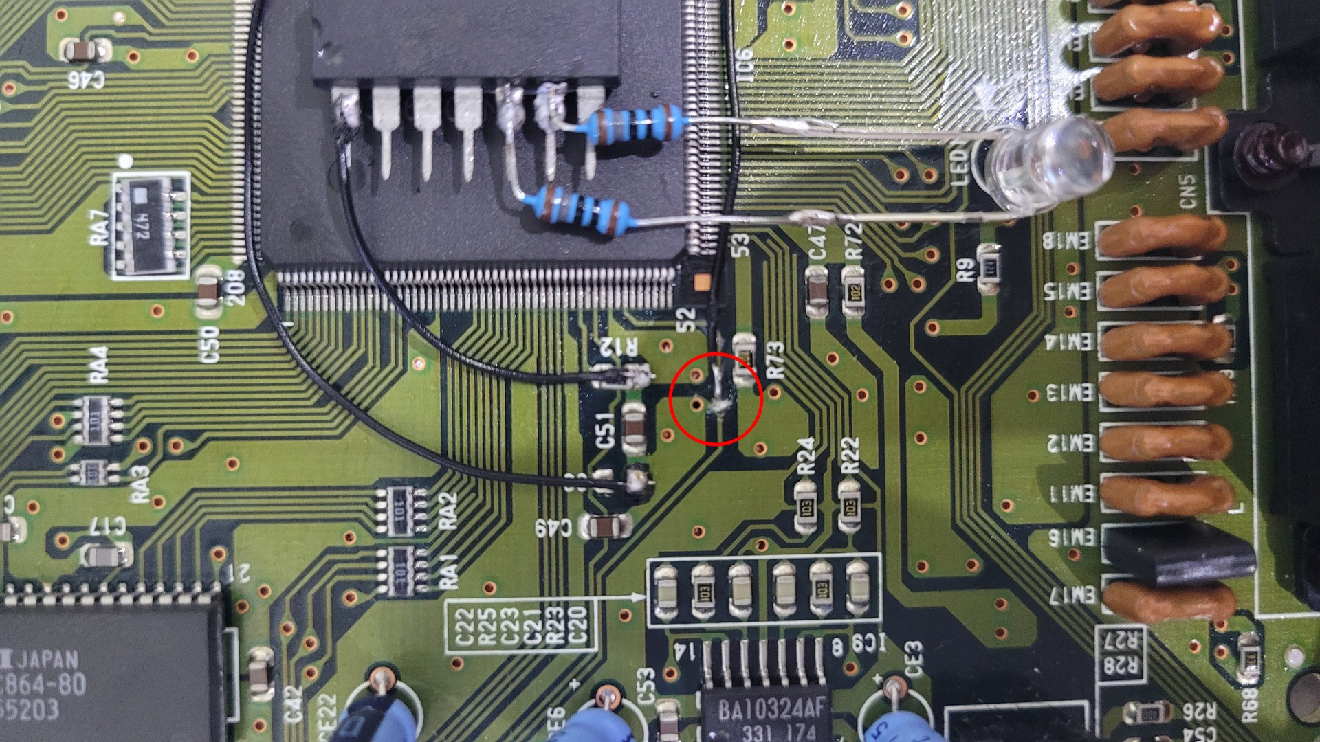
- Pin 12 : Switch 50 or 60 hz, directly from the trace, juste above R73 and below R12
- Pin 11 : Connection to the real reset of the console, directly from the trace
- Pin 9 : Region switch, directly from the trace
| Pin 1 – Vdd from R12 | Pin 14 – GND from C8 | Pin 13 – Reset in |
| Pin 12 – 50/60Hz | Pin 11 – Reset out | Pin 9 – Region Switch |
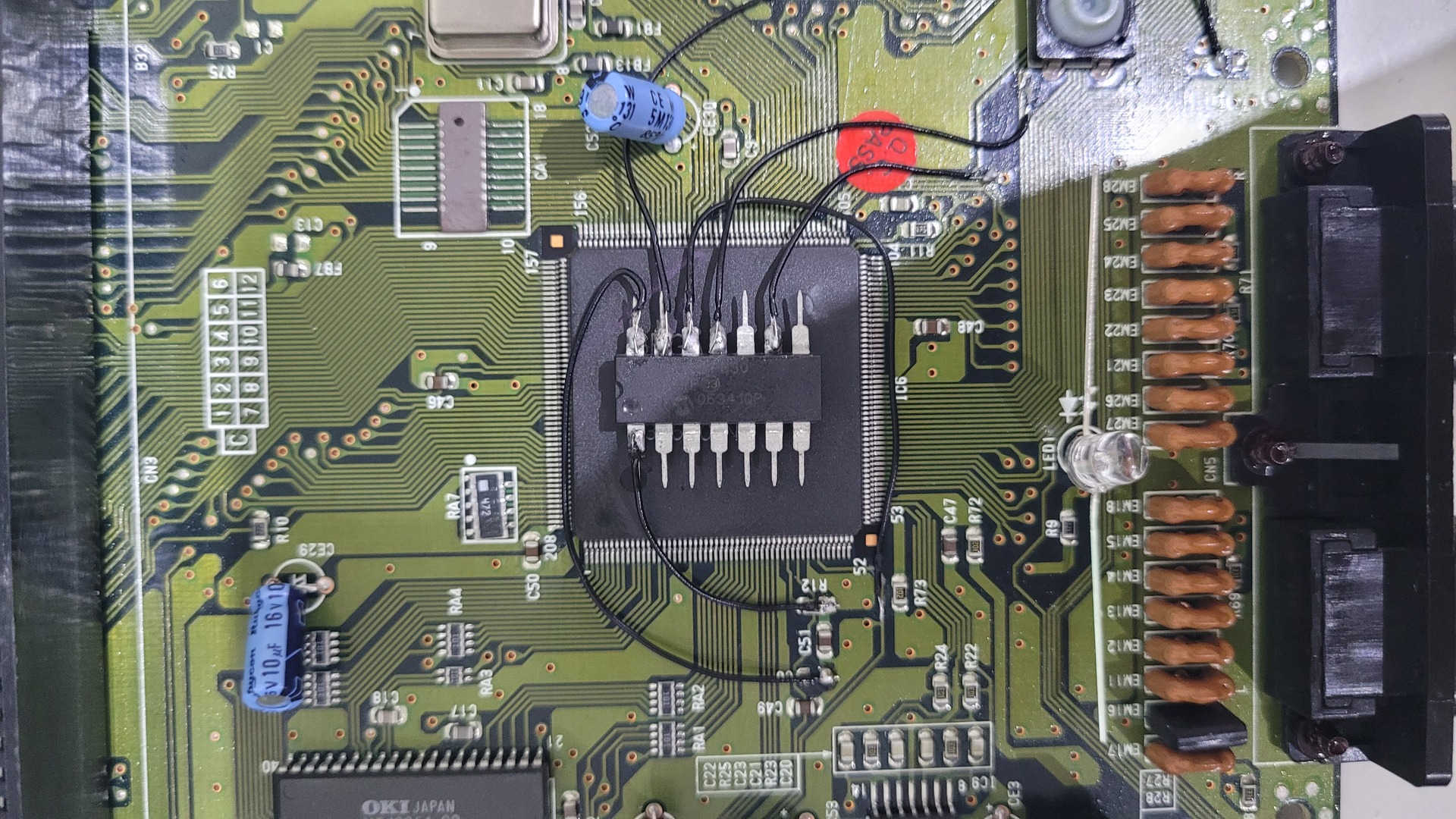
| Pin 5 and 6 : LED – Final Overview |
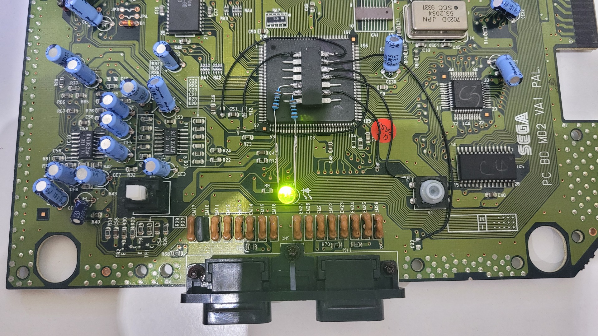
Cut traces and tests !
The mod is almost done, but do you remember the traces we scratch ? Now we have to cut the traces so the signal is handled exclusively by the PIC. This is the only destructive step, that’s why I did it at the end. Until this step, all can be reverted easily.
And here is the test. Depending on the LED wiring, the colour can be inverted. For me, green = EUR/PAL, red = JAP/NTSC, red+green = US/NTSC
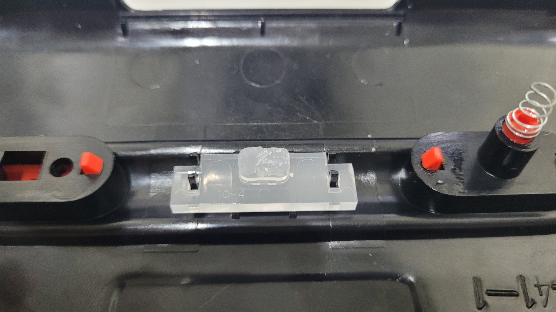
Remount and adapt for the new LED
OK, I previously said that only one step was destructive… I lied ! The kit I purchased contained a 5 mm LED whereas the original Megadrive 2 LED is a 3mm. So I had to cut the light conductor which is on the top part of the case.
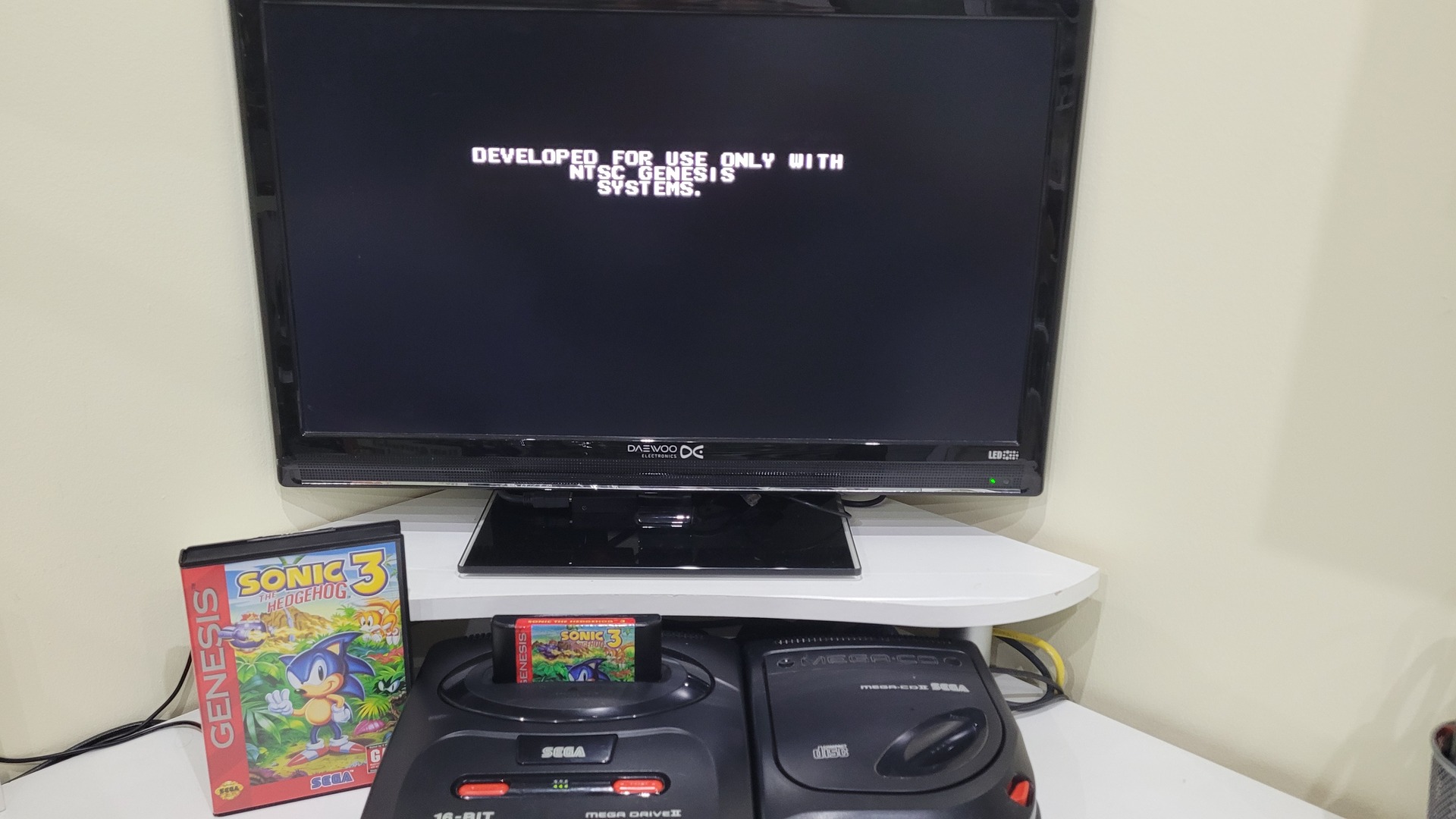
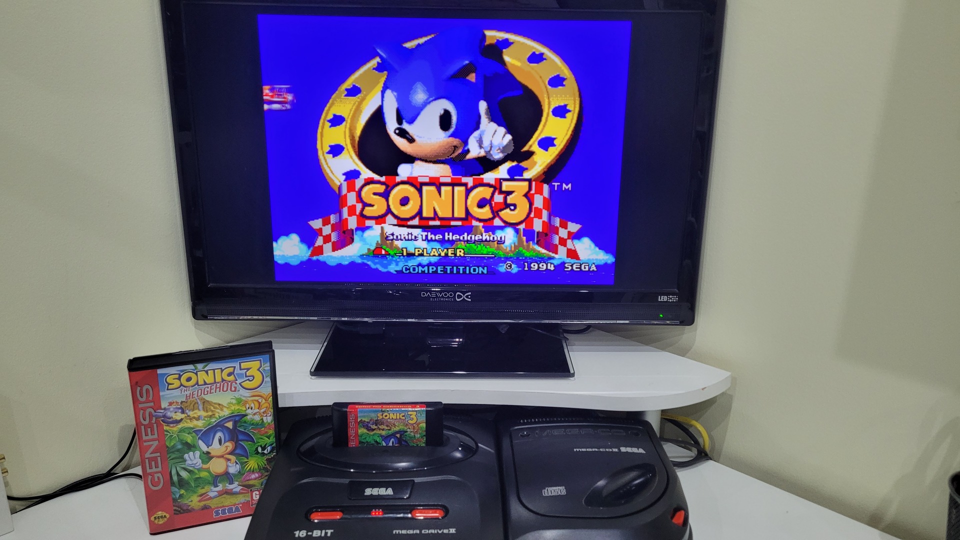
Final Result
Sonic 3 US version : on the left in PAL mode, on the right in US mode:
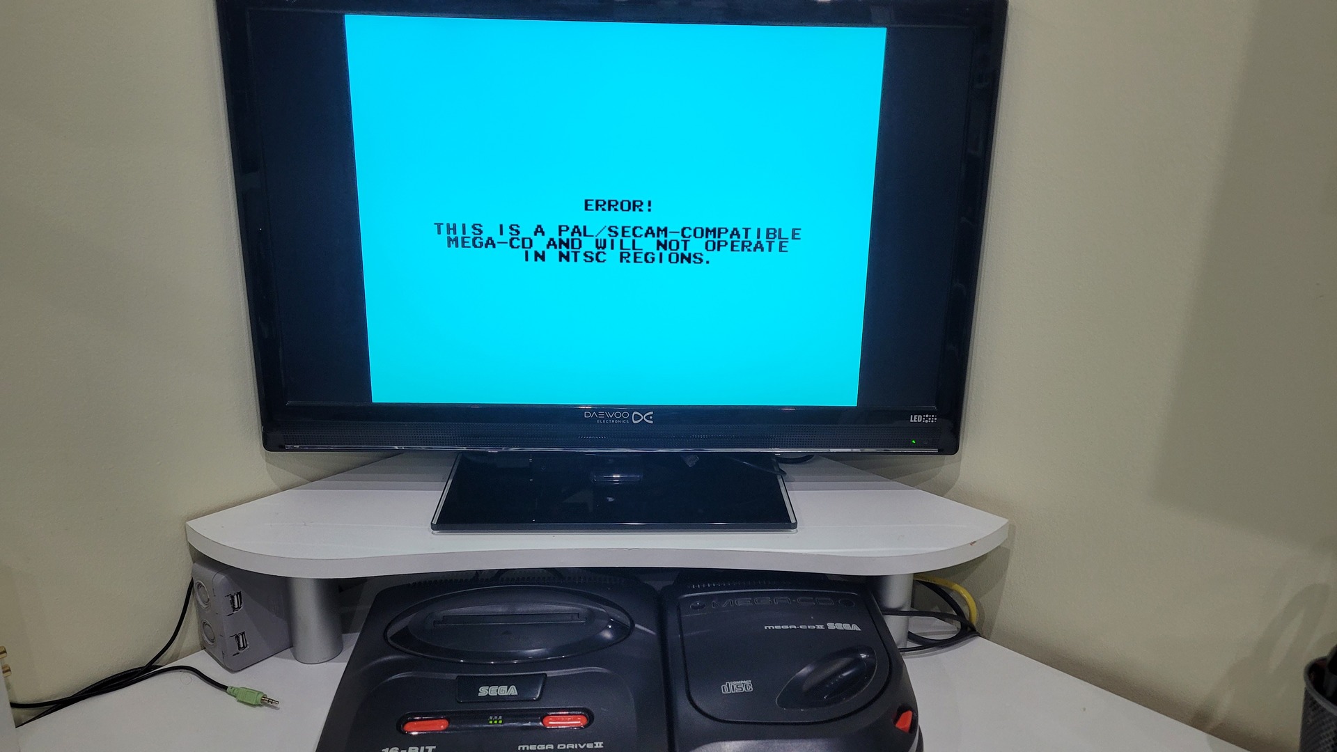
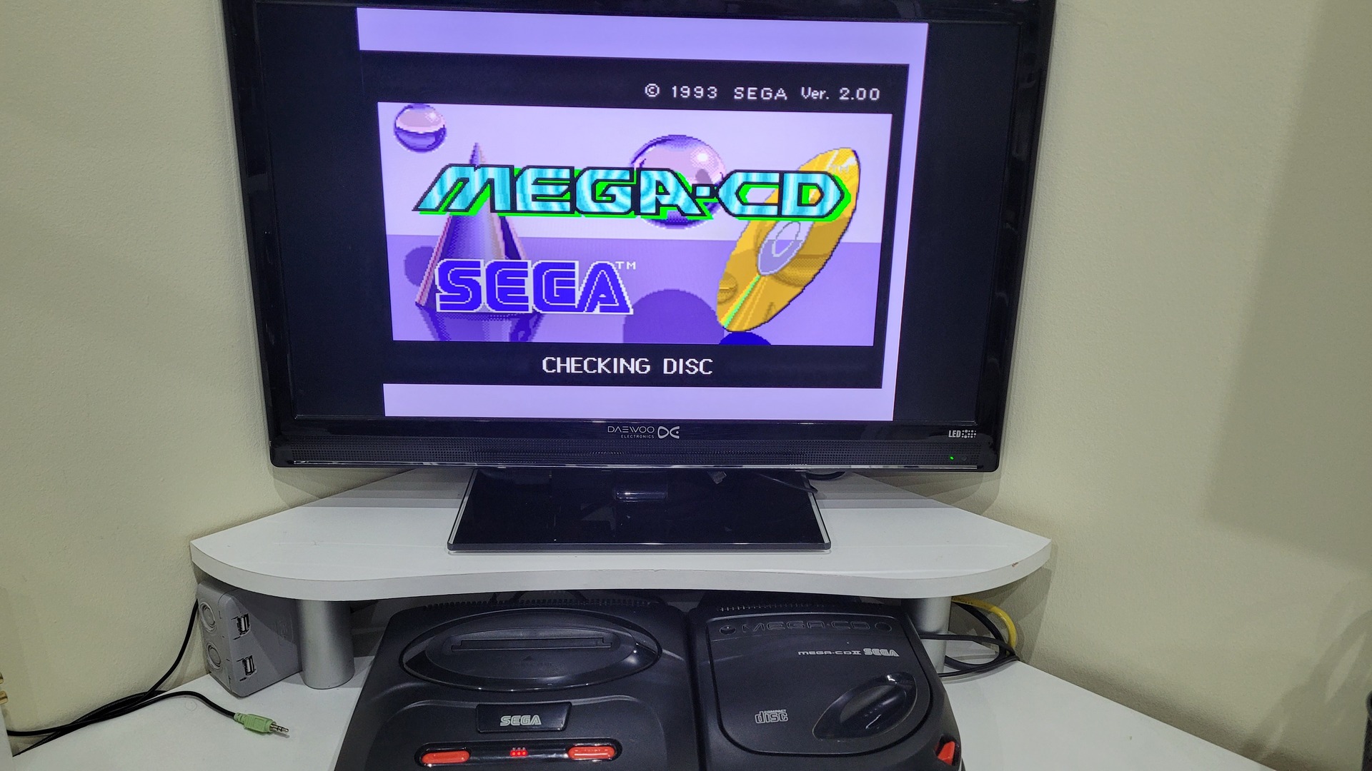
PAL MegaCD in Jap mode on the left, and PAL mode on the right:
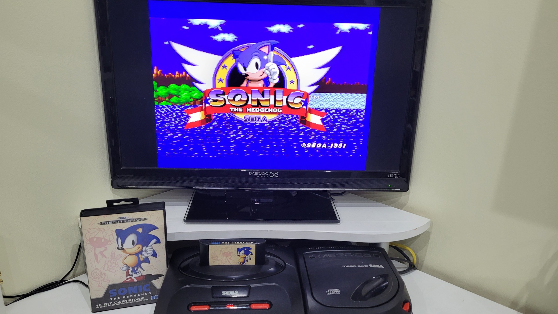
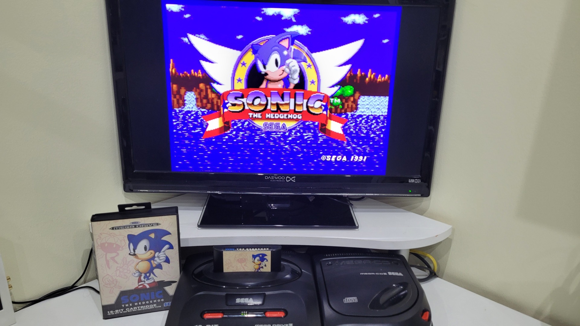
Sonic 1 in PAL mode on the left and in JAP mode in the right. You can see that in PAL mode, the aspect ratio is not the same.

[…] Removing the motherboard is pretty easy, and I have already coverred that the a previous article about a switchless region mod. […]